Description
The CUWB Viewer is a 3D visualization of the Ciholas Ultra-Wideband (CUWB) Real-Time Location System (RTLS). It provides a user interface displaying the locations of the CUWB devices, such as Anchors and Tags, in real time. The Viewer also presents basic system information, such as device status, statistics and more.
The CUWB Viewer is also compatible with our CDP Logging Tools and can render previously captured logs. Additional documentation for the CUWB RTLS system is available on CUWB.IO.
Installation
Host PC Requirements
- OS: Ubuntu 22.04 Jammy or Ubuntu 24.04 Noble
- CPU: Intel or AMD 64-bit architecture, 2.5GHz, dual core or better with SSE2 instruction set support
- GPU: Integrated graphics or dedicated graphics card with Vulkan 1.3+
- RAM: 4GB or better
- HD: 8GB or more (plus any additional required by logging)
PPA Installation and Setup
Follow the instructions below for CUWB Viewer installation.
- Follow best practices and review the install.sh script.
- bash <(wget -qO- "https://cuwb.io/docs/latest/assets/software-packages/install.sh")
- Paste into an Ubuntu 22.04/24.04 terminal and press Enter.
When prompted in the “CUWB Applications Selection”, ensure that CUWB Viewer is selected for installation.
Offline Installation
The CUWB Viewer can be installed on Host PCs that do not have PPA access. The following is a list of additional packages that may need to be installed on the Host PC before doing an offline installation of the CUWB Viewer. Use dpkg -l | grep <package_name> on the Host PC to verify whether each package is installed.
- liblttng-ust1
- liblttng-ust-common1
- liblttng-ust-ctl5
- dotnet-host-8.0
- dotnet-hostfxr-8.0
- dotnet-runtime-8.0
For instructions on how to obtain the DEB package, see Download Debian Packages for Software Packages. After downloading the package, transfer the DEB to a USB drive or another transfer method to the Host PC. Once the file has been transferred, navigate to its location and enter the following command in a terminal window to install the package:
sudo apt install ./cuwb-viewer-<version>.deb
Getting Started
Launch CUWB Viewer
Once the CUWB Viewer has been installed, launch the application through the Linux applications menu or by typing the following command into a terminal window:
cuwb-viewer
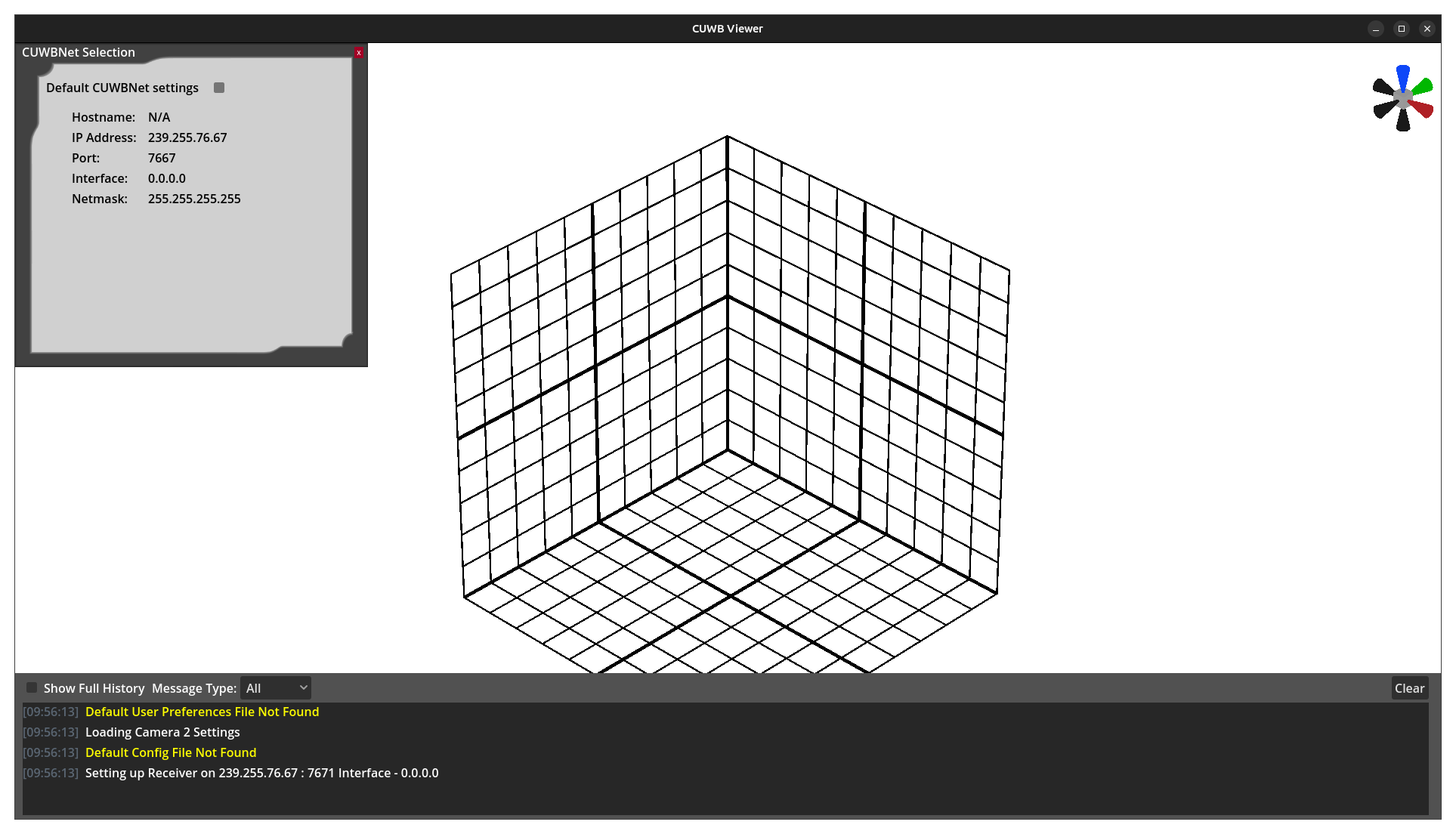
After the initial boot animation, the user will be presented with a blank screen displaying a 3D 10-meter grid, the CUWBNet selection window, and the message window at the bottom of the screen.
×
Network Configuration
On the initial run of the CUWB Viewer, no viewer configuration file will be loaded. A CUWBNet selection tool will appear populated with all available CUWBNets detected by the Viewer. By default, the Viewer listens on the CUWB Anchor Array configuration channel (IP 239.255.76.67, port 7671, interface 0.0.0.0), allowing the system to discover available CUWB Configurations.
Select an available CUWBNet and close the selection window. Once CDP data from the CUWBNet is received, the grid will expand and form around the representations of the system’s Tags and Anchors. See Network Settings and CUWBNet Selection for additional details.
Message Window
Along the bottom of the CUWB Viewer is a message window, which by default only appears when a message is posted. This can be configured in User Preferences.
Camera Configuration
The default Viewer camera angle is pointed at the center of the grid from the positive X, negative Y, and positive Z directions. See Camera Defaults for instructions on changing the default views or adding other custom views. The Camera Gizmo can also be used to create temporary viewing positions.
Grid Configuration
The default Viewer setup features a 10m x 10m x 10m cube with gridlines at each meter. This grid automatically expands to include all active devices and will shrink as devices move or stop reporting data. Additional settings including turning the grid off are available under Grid Configuration.
Devices
When connected to a running CUWBNet, devices will appear in the 3D scene as they begin reporting data. The way devices are displayed in the Viewer can be configured using either global settings or individual device settings, see Global Device Settings or Device Settings for more information.
By default, tags are represented as spheres and anchors are cubes. The devices are colored via the standard color scheme.
Objects
The Viewer is a valuable tool for modeling physical environments, primarily through the use of static 3D objects. See Objects for information on creating objects, modifying their properties, and adding custom objects.
CUWB Viewer Walkthrough
Message Window
Along the bottom of the CUWB Viewer is a message window that provides the user with system state changes, such as new devices appearing or CUWBNets going offline. By default, the window only appears when a message is posted. This behavior can be configured in User Preferences.
The window can be configured to display the following message options:
- Internal - Messages that the CUWB Viewer generates
- CDP - CDP messages received by the CUWB Viewer
- All - Messages from both the internal and CDP categories
- None - No messages will be printed
The message history can be shown in full by selecting the Show Full History checkbox.
Camera Gizmo

The Camera Gizmo is located in the upper-right corner of the Viewer screen. It provides a simple interface for visualizing the camera’s orientation and for moving and rotating the camera to face a specific axis. The Camera Gizmo displays the camera’s position and rotation relative to the scene and updates dynamically as the camera is adjusted.
The axis cones are color-coded to match their respective axes: the X-axis ir red, the Y-axis is green, and the Z-axis if blue. All negative axes are shown in black. When the mouse pointer hovers over a cone, it is highlighted in yellow. Left-clicking a cone adjusts the camera’s position to align parallel with the selected axis and rotates the view to the nearest 90-degree orientation.
Configurations
A configuration can be created through the File menu to quickly save and reload settings, objects, images, and devices. Configurations may be saved by overwriting the default configuration or by creating a new configuration file.
File Menu Options
| Submenu | Description |
|---|---|
| Save Configuration | Saves the current configuration, overwriting the default configuration file. |
| Save Configuration As… | Opens file browser to save the current configuration as a new file. |
| Load Configuration | Opens a file browser to select and load a configuration file. |
Default Configuration
The default viewer configuration file, config.zip, can be found in the /usr/lib/cuwb/viewer/ folder. This file will load on boot and restore all settings that a user has saved for a given CUWB Anchor Network setup.
On the initial launch of the CUWB Viewer, no viewer configuration file will be loaded.
Edit Settings
Edit Menu Options
| Submenu | Description |
|---|---|
| Network Settings | Modify and add network configurations |
| CUWBNet Selection | Select available CUWBNets to connect to or disconnect from |
| User Preferences | Access the User Preferences Settings |
Network Settings
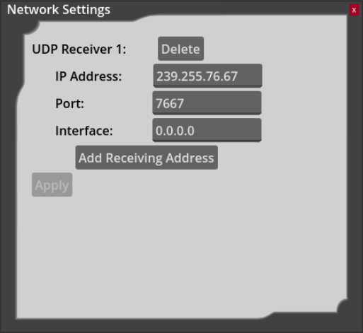
Network connection settings can be modified through this window if the user doesn’t want to use CUWBNet selection. Additionally, the CUWB Viewer can support more than one UDP Receiver.
Receiver 1 will default to the Anchor Array configuration channel (IP 239.255.76.67, port 7671, interface 0.0.0.0). This allows the system to discover available CUWB Configurations.
A UDP receiver must be setup for log playback. See Log Playback for additional information.
CUWBNet Selection
When the viewer is launched, the CUWBNet selection window will automatically appear, displaying all CUWBNets detected by the system. Multiple CUWBNets can be selected.
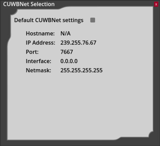
To prevent the CUWBNet selection window from appearing when the Viewer application boots, save the configuration using the
File -> Save Configurationmenu item. This will save the selected CUWBNets to the default viewer configuration. To return to the CUWBNet selection window selectEdit -> CUWBNet Selectionfrom the menu.
Once a CUWBNet is selected and the viewer begins receiving CDP data, the grid will automatically expand and organize itself around the visual representation of the system’s Tags and Anchors.
User Preferences
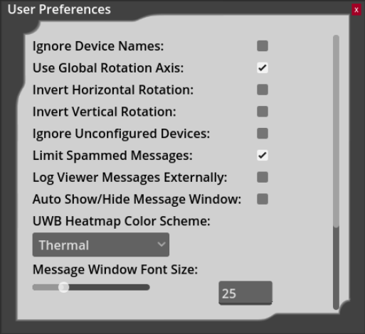
The Viewer provides several user-specific settings that can be adjusted independently of the active configuration.
| Setting | Default | Description |
|---|---|---|
| Ignore Device Names | Off | When enabled, the Viewer will ignore any names set by the CUWB Manager and display only each device’s serial number. |
| Use Global Rotation Axis | Off | When enabled, rotating the camera left or right will be around the nearest global “up” vector, rather than the “up” vector of the camera. When disabled, rotation is more similar to what is used in most CAD software. |
| Ignore Unconfigured Devices | Off | When enabled, all data received from devices marked as unconfigured in the CUWB Manager will be ignored. |
| Limit Spammed Messages | On | When enabled, frequently generated internal Viewer messages will be condensed into a single entry in the format “(x) Message Contents”, where x is the number of messages that were suppressed. |
| Log Viewer Messages Externally | Off | When enabled, all messages displayed in the Viewer message window will also be logged with any other Viewer log messages. |
| Auto-Hide Message Window | On | When enabled, the message window will automatically hide itself after 15 seconds of inactivity and will reappear when a new message is displayed. When disabled, the message window will only be shown or hidden using the assigned keybind. |
| UWB Heatmap Color Scheme | Green to Red | Coloring option used by UWB Heatmap Mode. Available options include “Green to Red”, “Thermal”, and “Blue Monochrome.” See Heatmap Mode for additional details. |
| Message Window Font Size | 16 | Adjustable setting that controls the size of text inside of the message window. Values are accepted in the range of 1 to 100. |
| Device Serial Numbers Scale | 3 | Adjustable setting that controls the size of the device’s serial number labels. Values are accepted in the range of 1 to 10. |
| Max Framerate | 60 | Target frame rate of the Viewer. The Viewer will attempt to match this value as closely as possible. Accepts values from 0 to 500, with 0 representing no maximum (i.e. the Viewer will run at the fastest possible frame rate). |
Don’t forget to click apply to apply the selected settings.
View Options
View Menu Options
| Submenu | Description |
|---|---|
| Configure Grid | Configure the grid size and visibility |
| Camera Defaults | Set default camera view and perspective |
| UWB Heatmap Mode | Select device and enable UWB Heatmap mode |
| Toggle Measurement Mode | Enables or disables 3D measurement mode |
| Clear Measurements | Deletes all 3D measurements |
| Pause/Play | Pauses or Resumes CDP traffic |
Grid Configuration
The default Viewer setup features a 10m x 10m x 10m cube with gridlines at 1-meter intervals. This grid can either be configured to automatically size based on the devices being tracked, or it can be manually configured to a fixed size.
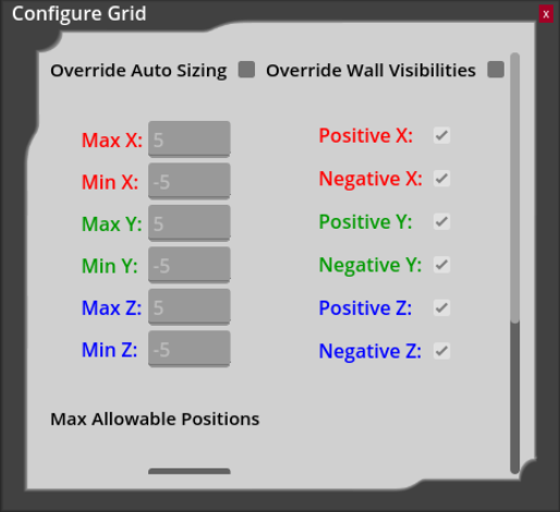
Override Auto Sizing
By default, the Viewer grid automatically expands to accommodate all active devices and will contract as devices move or stop reporting data. This behavior can be overridden by enabling Override Auto Sizing. When enabled, the position of each grid wall can be manually configured using the corresponding input fields.
Disabling the
Override Auto Sizingwill return the grid to its default size settings.
Override Wall Visibilities
The visibility of each individual grid wall can also be configured by enabling Override Wall Visibilities and then unchecking the box of the corresponding wall to make it invisible.
Disabling the
Override Wall Visibilitieswill return the grid to its default visibility settings.
Max Allowable Positions
The maximum allowed position values for devices can also be configured in the configure grid window. Minimum and maximum limits can be set for each axis using the text boxes under “Max Allowable Positions.” If a device exceeds any of these limits, its position will be ignored and a warning will be displayed in the message window.
Camera Defaults
The default view used at startup can be configured in View -> Camera Defaults. A radio button under “Default” selects the camera view used on boot (positions 0 through 9). In addition, each camera position includes a checkbox under “Perspective” that determines whether the view is rendered in perspective or orthographic mode.
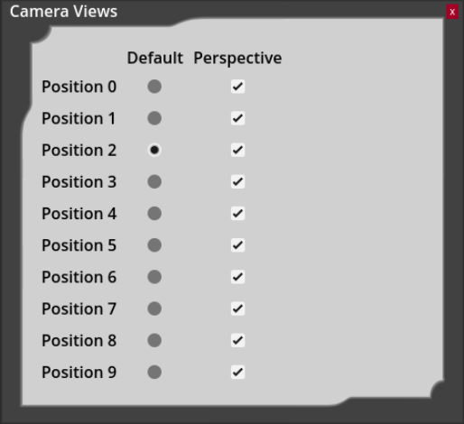
The default camera positions can be overridden by saving the current camera view. Pressing Ctrl + a number key (0 through 9) will save the current camera settings to that position. Pressing the corresponding number key restores the saved view. Saved camera positions can be reset to their defaults from View -> Camera Defaults by selecting the “Reset” button next to the desired position. This button only appears after a custom view has been saved.
Color Modes
Standard Colors
The color of the device is used to indicate the connectivity and synchronization status.
| Color | Description | |
|---|---|---|
| Gray | Gray | Inactive |
| Red | Red | Error |
| Yellow | Yellow | Warning |
| Green | Green | Good |
| Blue | Blue | Located |
The above chart and the currently set heatmap color scheme can be found under Help -> Color Legend.
Heatmap Colors
Enabling this mode changes the coloring of anchors to reflect their usage in tracking the selected tag. The location algorithm weights data from anchors depending on the quality of the tag beacon reception. Anchor coloring in heatmap mode reflects the relative anchor weighting used by the location algorithm. The table below describes the heatmap color scheme.
| Color Scheme | Description | ||
|---|---|---|---|
| Green to Red | Thermal | Blue Monochrome | |
| Fluorescent Green | Sun Yellow | Ice Blue | 90-100% |
| Yellow Green | Tangerine | Pale Blue | 80-89% |
| Dandelion | Pumpkin Orange | Cyan | 70-79% |
| Sun Yellow | Reddish Orange | Bright Sky Blue | 60-69% |
| Orange Yellow | Tomato | Cerulean | 50-59% |
| Tangerine | Magenta | Ocean Blue | 40-49% |
| Fire Engine Red | Indigo | Navy | 0-39% |
| Gray | No Data | ||
| Black | Bad Status | ||
Measurement Mode
The distance between devices and objects can be measured in real time using the Measurement Mode tool. To enable it, select View -> Toggle Measurement Mode. When active, a ruler icon will appear in the top-right corner of the view. Once enabled, select two devices or objects using the left mouse button to draw a red, three dimensional line between them that displays their distance in meters.
To return to normal operation, disable Measurement Mode via View -> Toggle Measurement Mode. The ruler icon will disappear, and the left mouse button will return to selecting devices or objects. Measurement lines can be selected with the left mouse button, turning a brighter shade of red, and then deleted with the Delete key. Selecting View -> Clear Measurements will delete all existing measurement lines.
Play / Pause
The CUWB Viewer allows users to pause the stream of data using the play / pause command. This can be found under View -> Play/Pause or by hitting the space key.
Devices
When connected to an active CUWBNet, devices will appear in the 3D scene as they begin reporting data. Their display within the Viewer can be configured using the global settings or individual device settings. See Device Settings or Global Device Settings for additional information.
Devices Menu Options
| Submenu | Description |
|---|---|
| Global Device Settings | Configurable settings applied to all devices, see Global Device Settings |
| Device List | Displays all anchors and tags and allows access to their information or settings windows |
| Find Device | Searches for a device and moves the view to its location |
| Clear Devices | Clears all devices from the view |
| Selected Device Info1 | Opens the information window for the selected device |
| Selected Device Settings1 | Opens the settings window for the selected device |
1. Option only visible when a device is selected.
Global Device Settings
Device options can be configured individually per device through Device Settings or globally for all devices through the “Global Device Settings”.
The device configuration options supported by the system are as follows:
| Option | Default | Description |
|---|---|---|
| Serial Numbers | All on | Toggle serial number display. Can be set to all devices, Tags only, or Anchors only |
| Device Resizing | Auto-Scale | Automatically resizes devices or allows manual adjustments of device size |
| Tag Time Until Gray | 5 s | Time in seconds before a Tag turns gray after it’s data is no longer received |
| Tag Time Until Remove | 10 s | Time in seconds before a Tag is removed from display after turning gray |
| Tag Trails | 2 s | Displays the Tag’s path over a configurable time period in seconds |
| Tag Smoothing | 1 packet | Number of tag position reports averaged for display |
| Quality Filter2 | 0 | Minimum accepted value for a position’s quality; positions below this value are not displayed |
| Orientation Display | Off | Enables device rotation using quaternions and changes tag models to 3D arrows |
| Device Model | Default Model | Selects the 3D model used for the device |
| Color | Default | Sets the individual color for the device |
2. This value can only be set via the Global Device Settings window found in Devices->Global Device Settings.
Device List
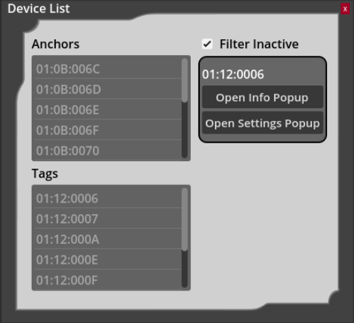
To view all devices in the Viewer, open the Devices -> Device List window. This window displays both Anchors and Tags, sorted by serial number. Selecting a device highlights it as if you clicked it directly and provides options to open its Info or Settings window. To show only currently active devices, enable the Filter Inactive option.
Find Device
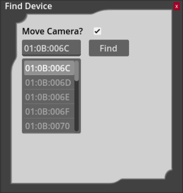
To locate a specific device in the Viewer, open the Devices -> Find Device window. Typing a serial number in the textbox will open a dropdown list of matching device serial numbers. When a valid serial number is entered, either by typing or selecting an option from the dropdown, click “Find” to highlight corresponding device as if it were clicked directly.
If the “Move Camera” option is enabled, clicking “Find” will also center the camera on the selected device.
Clear Devices
To remove all devices from the Viewer, select Devices -> Clear Devices option. This clears both active and inactive devices from the Viewer. Devices will reappear automatically once they are detected again.
Device Info
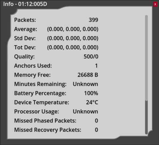
The device info panel provides detailed information for a selected device. Anchors and tags have different displayed settings in the info panels.
Tag Settings
| Setting | Description |
|---|---|
| Packets | Count of received packets |
| Average | Average position of Tag in XYZ |
| Std Dev | Standard deviation of the Tag position in XYZ |
| Tot Dev | Total deviation of the Tag position in XYZ |
| Anchors Used | Count of Anchors used to resolve position calculation |
| Memory Free | Available memory on the Tag |
| Minutes Remaining | N/A |
| Battery Percentage | Percentage of battery available for use by the Tag |
| Device Temperature | Temperature in degrees Celsius |
| Processor Usage | N/A |
| Missed Phase Packets | Number of missed Command windows while in phase |
| Missed Recovery Packets | Number of missed Command windows while attempting to recover from being out of phase |
| Flags | See Flags |
| Quality | An assessment of the quality of the most recently calculated position |
| Accelerometer3 | Displays Accelerometer XYZ readings |
| Gyroscope3 | Displays Gyroscope XYZ readings |
| Magnetometer3 | Displays Magnetometer XYZ readings |
| Quaternion3 | Displays Quaternion WXYZ |
3. Only available on supported hardware. See device datasheets for sensor support.
Anchor Settings
| Setting | Description |
|---|---|
| Position | XYZ position of Anchor |
| Synchronization | Reports if Anchors have TX or RX sync |
| Connectivity | Reports if Anchors have UWB or Ethernet connectivity |
| Memory Free | Available memory on the tag |
| Minutes Remaining | N/A |
| Battery Percentage | N/A |
| Device Temperature | N/A |
| Processor Usage | N/A |
| Missed Phase Packets | N/A |
| Missed Recovery Packets | N/A |
| Flags | See Flags |
| Accelerometer4 | Displays Accelerometer XYZ readings |
| Gyroscope4 | Displays Gyroscope XYZ readings |
| Magnetometer4 | Displays Magnetometer XYZ readings |
| Quaternion4 | Displays Quaternion WXYZ |
4. Only available on supported hardware. See device datasheets for sensor support.
Flags
The following flags are listed when selecting View on the Device Info panel for a Tag or an Anchor.
| Flag Field | Description |
|---|---|
| Full Field | Provides the full field of the flag packet |
| Powered | Indicates if the device is receiving external power |
| Charging | Indicates if the device is charging its battery |
Device Settings
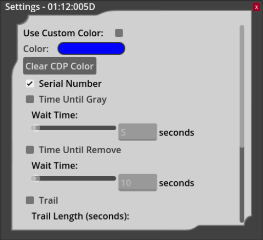
Some of these settings are duplicated in the Global Device Settings options. Individual Device Settings take priority and will override the corresponding global setting when both are configured.
| Option | Default | Description |
|---|---|---|
| Use Custom Color | Off | Check to use custom color for this device |
| Color | Blue | Select custom color from color picker |
| Serial Numbers | On | Toggle serial number display for this device |
| Trail | Off | Check to display Tag’s historical path |
| Trail Length | 2 | Show tag path over configurable period in seconds |
| Smoothing | Off | Check to enable smoothing for this device |
| Smoothing (Packets) | 1 packet | Set the number of Tag position reports to average for display |
| Size Scale | 0.25 | Scale the device model |
| Model | Default Model | Set the 3D model used by the device |
Objects
The Viewer is a valuable tool for modeling physical environments, largely through the use of static 3D objects.
By default, tags are represented as spheres and anchors are cubes. The objects are colored via the standard color scheme.
Objects Menu
| Submenu | Description |
|---|---|
| Import Object | Import primitive 3D objects, images5, or custom 3D models6 |
| Object List | View list of imported objects and open their properties window |
| Delete Selected Object7 | Delete the currently selected object |
| Selected Object Properties7 | Opens selected object’s properties window |
5. Supports .JPG, .PNG, .BMP, .SVG, .WEBP, .TGA, .HDR, .EXR, .KTX, and .DDS
6. Supports .GLTF and .GLB
7. Option only visible when an object is selected.
Creating Objects
Objects can be added to the Viewer via the Objects -> Import Object window. Imported objects are saved and loaded as part of your configuration. A variety of object types are supported, including primitive 3D shapes (such as cubes, spheres, and cones), as well as images and custom 3D models.
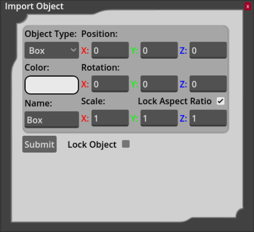
All objects have a corresponding type, color, position, rotation, scale, and name that determine their look in the 3D scene. These values can be changed, which will update the transparent preview of the specified object in the 3D view:
- Object Type - Box, sphere, cylinder, cone, capsule, prism, torus, image or custom
- Position - Define the X,Y, and Z position for the object
- Color - Brings up color selection menu and color picker
- Rotation - Define the X,Y, and Z rotation for the object
- Name - Give the object a name, helpful if using repeated objects
- Scale - Scale the object in X,Y, or Z
- Lock Aspect Ratio - Ensures that changing one axis of the scale values updates the rest of the values proportionally
- Lock Object - Prevents an object from being selected with the mouse or changed once it is created, until that object is unlocked
Once the object’s settings have been specified, press the “Submit” button to create the object.
Object Properties
Once created, an unlocked object can be selected with the mouse to open its Properties window. This window can also be accessed from the Objects -> Selected Object Properties menu.
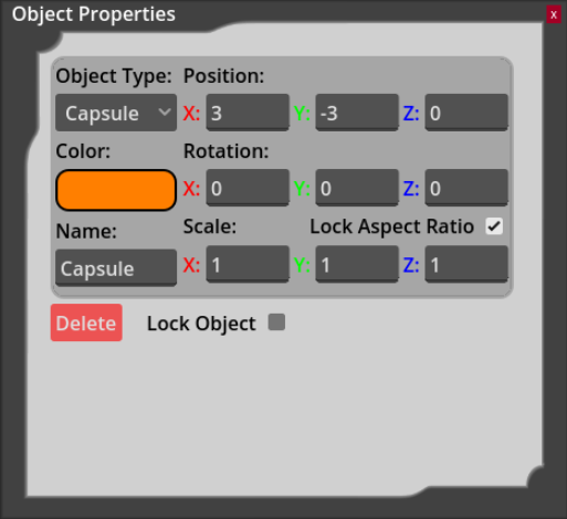
Changing these values will update the already created object. A “Delete” button is available to remove this selected object from the CUWB Viewer.
If an object is locked, it must be selected from the
Object Listto access its Properties window. This is the only way to unlock a locked object.
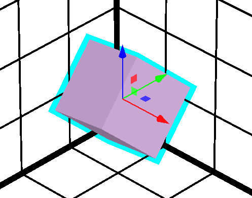
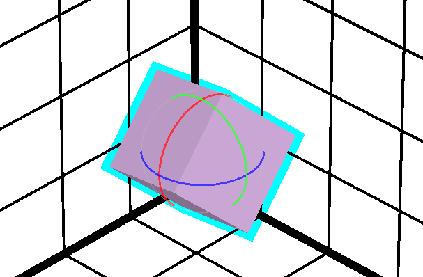
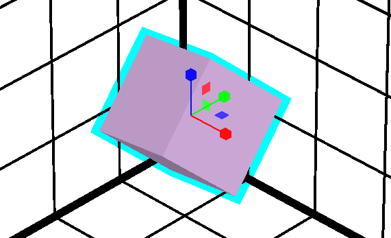
Object Gizmo
The Object Gizmo provides tools for translating, rotating, and scaling objects within the scene. When an object is selected with the mouse, the Object Gizmo appears and reflects the currently active tool.
 |
 |
 |
|---|---|---|
| Translation Gizmo | Rotation Gizmo | Scaling Gizmo |
To switch between tools, press the T for translation, R for rotation, and S for scaling. Clicking and dragging the red, green, or blue components of the Object Gizmo applies the corresponding operation along the X, Y, or Z axis. Holding the Ctrl key while dragging the mouse snaps the operation to whole number increments. See Object Shortcuts for additional keyboard shortcuts.
Custom Objects
When creating an image or custom object, an associated asset must be imported for that object.
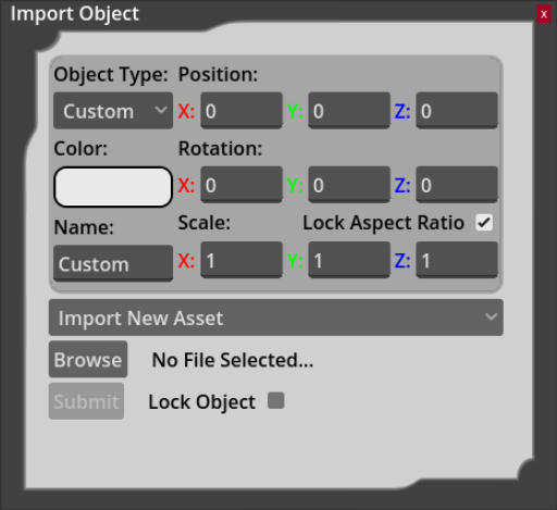
When selecting a custom object type, a dropdown list appears showing all previously imported assets of that type. These can be selected to reuse existing assets. If the “Import New Asset” option is selected, a “Browse” button appears allowing you to open a system file dialog and select the corresponding asset. Imported assets are saved as part of the Viewer configuration.
Custom assets that are large or complex may take longer to load and can reduce Viewer performance.
Custom 3D models can also be used in place of the anchor’s cube or the tag’s sphere. See Device Model under Device Options.
Object List
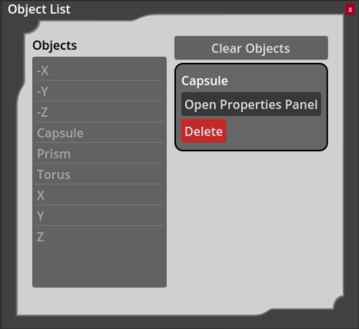
To view all objects, open the Objects -> Object List window. This window displays all objects currently in the scene. Selecting an object from the list highlights the object as if clicked on with the mouse, and enables options to open its Properties window or deleting it. The object list also includes a “Clear Objects” button, which will delete all of the objects in the scene. Deleting or clearing objects cannot be undone unless the Viewer configuration is saved and not overwritten.
Help & Other Resources
Help Menu Options
| Submenu | Description |
|---|---|
| Keyboard Shortcuts | View the keyboard shortcuts |
| Color Legend | View the color legend for the devices |
| Viewer Help | Open the documentation page |
| About CUWB Viewer | Display Viewer information |
| External Licenses | 3rd-party software Licensing information |
Color Legend
This menu option opens up the configured standard color and heatmap mode colors. See Color Modes for the available color mode options.
Mouse Controls
While not a menu option, this section outlines the available mouse controls for the CUWB Viewer.
Drag View
The camera view may be adjusted using the middle or right mouse button. Holding either button and dragging the mouse moves the view in the same direction as the drag.
Rotate View
To rotate the view, hold shift while dragging the mouse with the middle or right mouse button held. When the Shift is pressed, a sphere appears indicating the point of rotation, which is selected relative to the current cursor location. If no object is under the mouse, the rotation point is set to the center of the visible grid. If the grid center is not visible, the rotation point defaults to the center of the screen.
Zoom View
To zoom in and out, scroll the mouse wheel.
Device/Object Selection
The left mouse button is used to select devices or objects. Once selected, they can be configured through the Selected Device Settings or Selected Object Properties windows, or by pressing ‘C’. To view current statistics for a device, choose the Selected Device Info or press ‘I’ on the keyboard while the device is selected.
Selected devices and objects are highlighted in cyan, and any associated a serial number or name is displayed in magenta.
Keyboard Controls
Camera Shortcuts
| Description | Keyboard |
|---|---|
| Switch Camera Perspective | - |
| Zoom to Fit | = |
| Go to Camera Position 0-9 | 0-9 |
| Set Camera Position 0-9 | Ctrl+0-9 |
| Pan Down | Down |
| Pan Left | Left |
| Pan Right | Right |
| Pan Up | Up |
| Roll Left | Ctrl+Left |
| Roll Right | Ctrl+Right |
| Rotate Down | Shift+Down |
| Rotate Left | Shift+Left |
| Rotate Right | Shift+Right |
| Rotate Up | Shift+Up |
| Zoom In | Ctrl+Up |
| Zoom Out | Ctrl+Down |
| Open Camera Defaults Window | Ctrl+C |
General Shortcuts
| Description | Keyboard |
|---|---|
| Close Window/Toggle Navbar Visibility | Esc |
| Pause/Resume | Space |
| Show/Hide Message Window | M |
| Save Configuration | Ctrl+S |
| Save Configuration As | Ctrl+Shift+S |
| Load Configuration | Ctrl+L |
| Open User Preferences Window | Ctrl+U |
| Open Configure Grid Window | Ctrl+G |
| Open UWB Heatmap Mode Window | Ctrl+V |
| Open Viewer Documentation | F1 |
| Open About Window | F2 |
| Open Keyboard Shortcuts Window | Ctrl+K |
| Open Color Legend Window | Ctrl+J |
Network Shortcuts
| Description | Keyboard |
|---|---|
| Open Network Settings Window | Ctrl+N |
| Open CUWBNet Selection Window | Ctrl+B |
Device Shortcuts
| Description | Keyboard |
|---|---|
| Open Global Device Settings Window | Ctrl+T |
| Open Selected Device Info Window | I |
| Open Selected Device Setting Window | C |
| Open Device List Window | Ctrl+D |
| Open Find Device Window | / |
| Clear Devices | Ctrl+Esc |
Object Shortcuts
| Description | Keyboard |
|---|---|
| Open Selected Object Properties Window | C |
| Open Import Object Window | Ctrl+O |
| Open Object List Window | Ctrl+Q |
| Snap Object Gizmo | Ctrl |
| Switch to Translation Tool | T |
| Switch to Rotation Tool | R |
| Switch to Scale Tool | S |
| Delete Selected Object | Delete |
Measurement Shortcuts
| Description | Keyboard |
|---|---|
| Toggle Measurement Mode | Ctrl+M |
| Delete Selected Measurement | Delete |
| Clear All Measurements | Ctrl+Delete |
Log Playback
To use the CUWB Viewer with CDP Log Playback, first setup the CDP Log Playback.
Then, set the CUWB Viewer to listen to the CDP Player IP address and port in the Network Settings.
The log playback does not support using CUWBNet selection window to locate the playback stream.
Play the stream from the CDP player, and the data will populate the CUWB Viewer as if it were a live network.
Revision
| Version | Date | Change Description |
|---|---|---|
| 5.0.2 | 2026-05-01 | Minor edits for reader clarity, updating images |
| 5.0.1 | 2025-11-14 | Updating Host PC requirements |
| 5.0.0 | 2025-10-31 | Initial Preliminary Release |
APPENDIX A : License Terms and Conditions
General Terms and Conditions of Purchase/Service
These General Terms of Purchase/Service are a legal Agreement between you and Ciholas, Inc. (“Ciholas”), and govern your use of all Ciholas services and products, which include, but are not limited to, CUWB.io, Ciholas.com, and all Ciholas Products, Software, and Hardware. If you are accessing and/or using any of the Ciholas services and products on behalf of your employer or as an agent of a third party, your employer or third party is bound to these terms.
Please read these General Terms carefully. Your use of these services and products indicates that you have read, understand, and agree to be bound by the terms herein. Any attempt to set up, use, or install these products constitutes your assent to all the terms of this Agreement. If you disagree with this or any of our other policies, please do not install or use our services and products, and see our return policies for instructions regarding our 60-day Money-Back Guarantee. Written approval is not a prerequisite to the validity and enforceability of this Agreement. Ciholas reserves the right to amend and/or update these terms from time to time. Such modifications to this Agreement will be posted to the website and bundled with software revisions.
This Agreement constitutes the entire and exclusive Agreement between Licensor and Licensee regarding Ciholas services and products, unless modified and agreed to in writing by both parties. We may terminate or suspend access to our services and products at any time, without prior notice or liability, for any reason whatsoever, and without limitation if you breach the General Terms. All provisions of the General Terms shall survive termination, including, without limitation, ownership provisions, warranty disclaimers, indemnity, and limitations of liability. If any provision of this Agreement is deemed invalid or unenforceable, the remaining provisions shall remain in full force and effect.
Any customized services and products will be governed under a separate Customization Agreement.
Definitions
For purposes of this Agreement, the following terms shall have the following meanings, unless the context clearly requires otherwise:
“Agreement” means this General Terms of Purchase/Service Agreement and Technology License, any exhibits or appendices attached hereto, and any documents incorporated by reference.
“Buyer” means a person or entity that purchases or contracts to purchase products, services, or property from Ciholas.
“Ciholas” means Ciholas, Inc. including any entity controlled by Ciholas, Inc.
“End-User” means the person or entity that receives and uses Ciholas services and/or products.
“Firmware” means a code segment compiled into binary machine code that is embedded inside a device.
“Hardware” means the physical components of the Ciholas UWB Systems, such as anchors, tags, and supporting equipment.
“Indemnitee” includes, but is not limited to, all End-Users, Buyers, and/or Licensees.
“License Configuration” means a particular configuration or setting provided with Ciholas services and/or products for the purposes of meeting regulatory requirements, or ensuring performance to specification.
“Licensee” means any individual or entity who purchases or uses Ciholas services and/or products covered by this Agreement.
“Licensor” means Ciholas, Inc. including any entity controlled by Ciholas, Inc.
“Our” means Ciholas, Inc. including any entity controlled by Ciholas, Inc.
“Personal Identifiable Information (PII)” means any identifying information unique to you that is made available to Ciholas when you browse our sites, create accounts on our sites, purchase and use our services and products, and/or contact us through our support phone number /email.
“Products” means any goods and/or services provided by Ciholas that are covered under this Agreement.
“Services” means services ancillary to the support and operation of Ciholas Products, Software, Firmware, or Hardware.
“Software” means programs or sets of instructions, including associated source code, object code, documentation, and data, which enable End-Users to perform specific operations or series of operations.
“Technology License” means the License granted to the Licensee for the use of Ciholas services and products through this Agreement.
“We” means Ciholas, Inc. including any entity controlled by Ciholas, Inc.
“You” means the person or entity entering into this Agreement with Ciholas.
Technology License
Subject to the terms and conditions of this Agreement, Ciholas grants to you, the Licensee, a limited, non-exclusive, license to use CUWB Software and CUWB Hardware containing Ciholas’ Intellectual Property and patent-protected technologies. Ciholas remains the owner of all titles, rights, and interests in the CUWB Software, CUWB Hardware, and other Ciholas products.
Unless expressly stated otherwise, all Software constitutes original code and is subject to the License. Any use of the Software must be in compliance with the License. You acknowledge that the Software and the underlying ideas or concepts of the services and/or products are valuable intellectual property, and you agree not to, except as expressly authorized and only to the extent applicable by statutory law, attempt (or permit others to attempt) to decipher, decompile, disassemble, modify, or otherwise reverse engineer, or attempt to reconstruct or discover any original code, underlying ideas, algorithms, interoperability of the services, products, and Software by any means. Ciholas services, products, and Software are meant to be used in conjunction with one another and any attempt to circumvent this is a violation of this License.
It is a violation of this Agreement to alter any of the Ciholas products to change their designated capability with the intent, or resulting effect, of circumventing the license configuration. Any unauthorized modification violates the terms of service and may make the products illegal in certain jurisdictions (see Government, Regulation, Jurisdiction, and Export Control below).
You must never use Ciholas services and products in any way where the failure of said services and products could cause possible harm, injury, or death to you or others.
The Licensor may amend the License at any time and will post such modifications on our website. Changes are effective upon posting. The Licensee’s continued use of the Software after such posting constitutes acceptance.
Support
Under this Agreement, Ciholas is under no obligation to provide support for any product or service (such as, but not limited to, technical support, maintenance, upgrades, modifications, or new releases) unless otherwise specified by an additional Agreement.
Indemnification
Notwithstanding any other Agreements with Ciholas, the user shall indemnify, defend, and hold harmless the Licensor, its employees, successors, and heirs against any claim, liability, cost, damage, deficiency, loss, expense, or obligation of any kind or nature (including, without limitation, reasonable attorney’s fees and other costs and expenses of litigation) incurred by or imposed upon the indemnitees, or any one of them, in connection with any claims, suits, actions, demands, or judgments (including, but not limited to, actions in the form of tort, warranty, or strict liability) arising from the use of Ciholas software and products.
Force Majeure
Ciholas shall not be liable or responsible to you for any failure or delay in fulfilling or performing any term of this Agreement, when and to the extent that, such failure or delay is caused by or results from acts beyond Ciholas’ reasonable control, including, but not limited to, acts of nature, natural disasters, war, terrorism, labor disputes, supply chain disruptions, power outages, or governmental restrictions.
Government Regulation, Jurisdiction, and Export Control
Ciholas products are subject to governmental regulations and laws that may vary by state and country. By purchasing Ciholas products, you agree you will not ship, transfer, or export said products in any manner prohibited by law. You also warrant and agree that you are not located in, under the control of, or a national or resident of any of the countries defined by the Office of Foreign Assets Control, which include, but may not be limited to, Cuba, Iran, North Korea, and Syria. In addition to embargoes, other countries and/or regions may face restrictions under various U.S. export control regulations or be the target of sanctions governed by the Export Administration Act of 1979 (EAA), as amended, any successor legislation, the Export Administration Regulations (EAR), and the International Traffic in Arms Regulations (ITAR). You will comply in all respects with the export and reexport restrictions applicable to Ciholas products and will otherwise comply with the EAA, EAR, ITAR, and other United States laws and regulations in effect from time to time.
In addition to export regulations, the United States and other countries have laws and regulations governing the use of radio frequency (RF) devices. In the United States, such regulation is under Title III of the Communications Act of 1934, as amended, and regulated by the Federal Communications Commission (FCC). The FCC oversees all non-Federal uses of the radio frequency spectrum, while other regulatory bodies oversee RF devices in other countries’ jurisdictions. You agree that you will only use Ciholas products in the jurisdiction for which they were certified and will not exceed the products’ operational and use limitations as stated in the product manual. All Ciholas products are labeled as to their specific jurisdictional certification in accordance with the laws of that jurisdiction.
Governing Law
This Agreement will be governed by the laws of the State of Indiana, USA. Parties agree to attempt, in good faith, to resolve and settle any dispute arising out of this Agreement through negotiation between officially authorized representatives of each party. If the dispute is not resolved through negotiation, any litigation arising from the use of Ciholas services and/or products must be brought and resolved in the State of Indiana, USA.
60-Day Money-Back Guarantee
All standard Ciholas products not covered by another agreement have a 60-day Money-Back Guarantee. If for any reason the performance of any product is not acceptable, the product may be returned to Ciholas for a refund. Please note: bulk orders are not eligible for the money-back guarantee and cannot be canceled once the order is processed.
Shipping costs and any taxes and/or duties are not refundable and there is a 20% restocking fee for all returns under this policy. To be eligible for a refund, a customer must include an RMA# (see our return process) and dated proof of purchase with the item for return. The cost of the return shipment, including all taxes and duties, is at the buyer’s expense. Any product returned not in resalable condition will not be refunded.
Limited Warranty
Ciholas warrants that all Ciholas manufactured products, excluding software, will be free from any defect in materials or workmanship for a period of one year. Warranty begins on the date that an item is shipped from Ciholas to the buyer. The warranty is non-transferable and is extended only to the original buyers of this product when the product is used for the purpose for which it was intended. The one-year warranty covers only defects arising under normal use and does not include malfunctions or failures resulting from misuse, abuse, neglect, alteration, improper installation, acts of nature, tampering, or any repairs attempted by anyone other than Ciholas. During the one-year warranty period, the customer’s sole and exclusive remedy will be, at Ciholas’ sole discretion, the repair or replacement of the defective product, or refund of the purchase amount of the product. Ciholas reserves the right to substitute functionally equivalent new or serviceable used parts.
To be entitled to the rights provided by the one-year warranty, the customer must do the following:
- Contact Ciholas Technical Support at returns@ciholas.com or 1-844-595-TECH (8324).
- Provide in email/phone call, all model number(s), serial number(s), and proof of purchase for all items affected.
- If return/exchange is necessary, customer will be given a Returned Material Authorization (RMA) # to include with their return.
- The customer must then ship the item(s), at their expense (including all duties and taxes), to the address provided in the RMA authorization.
- Once a product arrives at Ciholas, return shipment of repaired or replaced product(s) or a refund will be sent to the customer. The method of return shipment is at Ciholas’ discretion and expense, except for applicable duties and taxes, which are the responsibility of the buyer.
Product Warranty Exclusions
Ciholas does not warrant or guarantee, and is not responsible for the following:
- Defects, failures, damages, or performance limitations caused in whole or in part by: (A) power failures and surges; fires; floods; acts of nature; excessive temperatures; corrosive environments; accidents; actions by third parties; or other events outside of Ciholas’ control; or (B) customer abuse; mishandling; misuse; negligence; improper storage, servicing, installation, or operation; or unauthorized attempts to repair or alter equipment in any way.
- Performance of the equipment when used in combination with equipment not purchased, specified, or approved by Ciholas.
- Consumable goods used with, or required by, Ciholas products.
- Alterations and/or modifications to any Ciholas equipment without Ciholas’ written authorization. Such action unconditionally VOIDS the Ciholas Agreement and Warranty.
- Installation of any software code, other than that provided and licensed by Ciholas. Any such installation onto any Ciholas product voids the one-year warranty, unless a written exemption is provided to the customer by Ciholas.
Disclaimer of Warranty
CIHOLAS SERVICES, PRODUCTS, AND ALL INFORMATION, CONTENT, MATERIALS, (INCLUDING SOFTWARE AND HARDWARE), AS WELL AS OTHER SERVICES MADE AVAILABLE THROUGH CIHOLAS, ARE PROVIDED ON AN “AS IS” AND “AS AVAILABLE” BASIS, UNLESS OTHERWISE SPECIFIED IN WRITING. CIHOLAS SERVICES INCLUDE ALL CIHOLAS OWNED AND OPERATED DOMAINS, INCLUDING, BUT NOT LIMITED TO, CIHOLAS.COM, CIHOLAS SHOP, CUWB.IO, AND ALL CIHOLAS PRODUCTS, SOFTWARE, AND HARDWARE. THE USE OF CIHOLAS SERVICES AND PRODUCTS IS AT THE USER’S SOLE RISK.
EXCEPT AS EXPRESSLY PROVIDED IN THE CIHOLAS WARRANTY POLICY STATEMENT, CIHOLAS HEREBY EXPRESSLY DISCLAIMS ALL REPRESENTATIONS, CONDITIONS, AND WARRANTIES, WHETHER EXPRESS OR IMPLIED, INCLUDING, BUT NOT LIMITED TO, IMPLIED WARRANTIES OF TITLE, MERCHANTABILITY, NON-INFRINGEMENT, AND FITNESS FOR A PARTICULAR PURPOSE. IN NO EVENT SHALL CIHOLAS BE LIABLE TO THE USER OR ANY OTHER PARTY FOR ANY DIRECT, INDIRECT, GENERAL, SPECIAL, INCIDENTAL, CONSEQUENTIAL, EXEMPLARY, OR OTHER INJURIES AND/OR DAMAGES ARISING OUT OF THE USE OR INABILITY TO USE CIHOLAS SERVICES AND PRODUCTS (INCLUDING, WITHOUT LIMITATION, DAMAGES FOR LOSS OF BUSINESS PROFITS, BUSINESS INTERRUPTION, LOSS OF INFORMATION, BREACH OR ANY OTHER PECUNIARY LOSS), OR FROM ANY BREACH OF WARRANTY. NOTWITHSTANDING ANYTHING TO THE CONTRARY CONTAINED IN THIS DISCLAIMER OF WARRANTY, IN NO CASE SHALL THE MAXIMUM AGGREGATE LIABILITY OF CIHOLAS TO THE USER EXCEED THE TOTAL AMOUNT OF THE ACTUAL FEES PAID BY THE USER TO CIHOLAS.
CIHOLAS IS NOT LIABLE FOR ANY CONDUCT OF ANY USER OF CIHOLAS SERVICES AND PRODUCTS, NOR FOR ANY APPLICATION OR USE OF CIHOLAS SERVICES AND PRODUCTS IN AN ILLEGAL MANNER, TO COMMIT AN ILLEGAL ACT, OR IN A JURISDICTION IN WHICH IT IS ILLEGAL OR UNAUTHORIZED TO USE THESE SERVICES AND PRODUCTS. IT IS THE RESPONSIBILITY OF THE USER OF CIHOLAS SERVICES AND PRODUCTS TO ESTABLISH THE LEGALITY OF ITS USE IN THE USER’S JURISDICTION.
Ciholas Standard Privacy Policy
Ciholas is committed to protecting your personal information and your right to privacy. If you have any questions or concerns about our policy or our practices with regards to your personal information, please notify Ciholas at info@ciholas.com.
The following is to inform you of our policies for collecting, using, and disclosing your Personal Identifiable Information (PII) made available to Ciholas when you browse our sites, create accounts on our sites, purchase and use our services and products, and/or contact us through our support email. By using any of our services and products, you agree to the collection and use of your PII in accordance with this and other policies contained in this Agreement.
Personal Identifiable Information Collected
In the CUWB.IO Shop, we collect personal information that you voluntarily provide to Ciholas when creating an account, posting messages, or otherwise contacting us. The PII that we collect depends on the context of your interactions with Ciholas and the choices you make regarding the information you provide. The PII you share is up to you and is not required for browsing any of our sites. However, if you want to create an account, purchase an item in our shop, and/or call/email our support staff, you may be asked for PII. The PII collected is encrypted using secure socket layer technology (SSL).
The PII we collect could include the following:
Name and Contact Data – First and last name, email address, postal address, phone number, and other similar contact data.
Credentials – Passwords and similar security information used for authentication and account access.
Payment Data – All payment data collected through the website is by a third-party payment processor (TPPP). Ciholas DOES NOT have access to any of the payment information that you provide to the TPPP. None of the TPPPs use any of your data for anything other than processing your payment and have their own privacy policies, which are as strict as or stricter than, those contained in this privacy policy. Ciholas and all Ciholas TPPPs use SSL/TLS encryption for securing data. All Ciholas TPPPs are PCI DSS compliant for payment processing standards.
Information Usage
We use your PII for the purposes listed above and to keep our site safe and secure (for example fraud monitoring and prevention) and to enforce our terms, conditions, and policies for our legitimate business purposes.
We may disclose your information where we are legally required to do so to comply with applicable law, judicial proceedings, court order, or legal process, such as in response to a court order or a subpoena.
We will not share, sell, rent, or trade any of your PII with any third parties.
Duration of PII Storage
We keep your information for only as long as necessary to fulfill the purposes outlined in this privacy policy unless otherwise required by law.
Keeping PII Safe
We have implemented appropriate technical and organizational security measures designed to protect the security of any personal information we process. However, given that the internet is not 100% secure, transmission of personal information to and from our sites is at your own risk. Only access our services, products, and sites within a secure environment.
Unique Privacy Rights
Based on the laws of some countries and states, you may have the right to request access to the PII we collect from you, change that information, or delete it in some circumstances. For more information on how to do that, please contact Ciholas at info@ciholas.com.
If you are visiting our sites from outside of the United States, please be aware that you are sending information (including PII) to the United States where our servers are located. That information may then be transferred within the United States or back out of the United States to other countries outside of your country of residence, depending on the type of information and how it is stored by us. These countries, including the United States, may not have data protection law as comprehensive or protective as those in your country of residence; however, our collection, storage, and use of your PII will at all times continue to be governed by this Privacy Policy.
Non-PII Information Automatically Collected
We automatically collect certain information through web analytics when you visit, use, or navigate any of our sites. This information does not reveal your specific identity, but may include device and usage information, such as your computer’s Internet Protocol (IP) address, browser type, browser version, operating system, referring URLs, country, location, the pages of our sites that you visit, the time and date of your visit, the time spent on those pages, and other similar statistics. This information is primarily needed to maintain the security and operation of our sites and for our internal analytics and reporting purposes.
We collect this information using cookies. Cookies are small pieces of text stored on a user’s computer. They can be accessed by the web server or the client computer, allowing the server to deliver information tailored to the user. Most web browsers are set to accept cookies by default. We use cookies to keep track of items stored in your shopping basket, to conduct research and diagnostics to improve our content, services, and products, to prevent fraudulent activity, and to improve security.
If you prefer, you may choose to set your browser to remove and reject cookies. This could affect the availability of certain features, services, or products on our sites. Most browsers allow you to turn off cookie collection in their Tools/Settings button under a Privacy tab.
These Terms of Service were last modified on 2025-11-11.
[End of Agreement]
APPENDIX B : Software License Attributions
This appendix documents the legal attributions for third party software and components included in the CUWB Viewer.
Gizmo3D
Gizmo3D
The MIT License (MIT)
Copyright (c) 2024 Christopher Charbonneau
The MIT License (MIT)
Permission is hereby granted, free of charge, to any person obtaining a copy of this software and associated documentation files (the “Software”), to deal in the Software without restriction, including without limitation the rights to use, copy, modify, merge, publish, distribute, sublicense, and/or sell copies of the Software, and to permit persons to whom the Software is furnished to do so, subject to the following conditions:
The above copyright notice and this permission notice shall be included in all copies or substantial portions of the Software.
THE SOFTWARE IS PROVIDED “AS IS”, WITHOUT WARRANTY OF ANY KIND, EXPRESS OR IMPLIED, INCLUDING BUT NOT LIMITED TO THE WARRANTIES OF MERCHANTABILITY, FITNESS FOR A PARTICULAR PURPOSE AND NONINFRINGEMENT. IN NO EVENT SHALL THE AUTHORS OR COPYRIGHT HOLDERS BE LIABLE FOR ANY CLAIM, DAMAGES OR OTHER LIABILITY, WHETHER IN AN ACTION OF CONTRACT, TORT OR OTHERWISE, ARISING FROM, OUT OF OR IN CONNECTION WITH THE SOFTWARE OR THE USE OR OTHER DEALINGS IN THE SOFTWARE.
Godot
Godot
The MIT License (MIT)
Copyright (c) 2014-present Godot Engine contributors.
Copyright (c) 2007-2014 Juan Linietsky, Ariel Manzur.
The MIT License (MIT)
Permission is hereby granted, free of charge, to any person obtaining a copy of this software and associated documentation files (the “Software”), to deal in the Software without restriction, including without limitation the rights to use, copy, modify, merge, publish, distribute, sublicense, and/or sell copies of the Software, and to permit persons to whom the Software is furnished to do so, subject to the following conditions:
The above copyright notice and this permission notice shall be included in all copies or substantial portions of the Software.
THE SOFTWARE IS PROVIDED “AS IS”, WITHOUT WARRANTY OF ANY KIND, EXPRESS OR IMPLIED, INCLUDING BUT NOT LIMITED TO THE WARRANTIES OF MERCHANTABILITY, FITNESS FOR A PARTICULAR PURPOSE AND NONINFRINGEMENT. IN NO EVENT SHALL THE AUTHORS OR COPYRIGHT HOLDERS BE LIABLE FOR ANY CLAIM, DAMAGES OR OTHER LIABILITY, WHETHER IN AN ACTION OF CONTRACT, TORT OR OTHERWISE, ARISING FROM, OUT OF OR IN CONNECTION WITH THE SOFTWARE OR THE USE OR OTHER DEALINGS IN THE SOFTWARE.
– Godot Engine https://godotengine.org
Godot Third Party
Third party licenses for Godot available as text file: Godot Third Party Licenses.
Ionicons
Ionicons
The MIT License (MIT)
Copyright 2013 Ionicons - https://iconfinder.com
The MIT License (MIT)
Permission is hereby granted, free of charge, to any person obtaining a copy of this software and associated documentation files (the “Software”), to deal in the Software without restriction, including without limitation the rights to use, copy, modify, merge, publish, distribute, sublicense, and/or sell copies of the Software, and to permit persons to whom the Software is furnished to do so, subject to the following conditions:
The above copyright notice and this permission notice shall be included in all copies or substantial portions of the Software.
THE SOFTWARE IS PROVIDED “AS IS”, WITHOUT WARRANTY OF ANY KIND, EXPRESS OR IMPLIED, INCLUDING BUT NOT LIMITED TO THE WARRANTIES OF MERCHANTABILITY, FITNESS FOR A PARTICULAR PURPOSE AND NONINFRINGEMENT. IN NO EVENT SHALL THE AUTHORS OR COPYRIGHT HOLDERS BE LIABLE FOR ANY CLAIM, DAMAGES OR OTHER LIABILITY, WHETHER IN AN ACTION OF CONTRACT, TORT OR OTHERWISE, ARISING FROM, OUT OF OR IN CONNECTION WITH THE SOFTWARE OR THE USE OR OTHER DEALINGS IN THE SOFTWARE.
Phosphor
Phosphor
The MIT License (MIT)
Copyright 2022 Phosphor - https://iconfinder.com
The MIT License (MIT)
Permission is hereby granted, free of charge, to any person obtaining a copy of this software and associated documentation files (the “Software”), to deal in the Software without restriction, including without limitation the rights to use, copy, modify, merge, publish, distribute, sublicense, and/or sell copies of the Software, and to permit persons to whom the Software is furnished to do so, subject to the following conditions:
The above copyright notice and this permission notice shall be included in all copies or substantial portions of the Software.
THE SOFTWARE IS PROVIDED “AS IS”, WITHOUT WARRANTY OF ANY KIND, EXPRESS OR IMPLIED, INCLUDING BUT NOT LIMITED TO THE WARRANTIES OF MERCHANTABILITY, FITNESS FOR A PARTICULAR PURPOSE AND NONINFRINGEMENT. IN NO EVENT SHALL THE AUTHORS OR COPYRIGHT HOLDERS BE LIABLE FOR ANY CLAIM, DAMAGES OR OTHER LIABILITY, WHETHER IN AN ACTION OF CONTRACT, TORT OR OTHERWISE, ARISING FROM, OUT OF OR IN CONNECTION WITH THE SOFTWARE OR THE USE OR OTHER DEALINGS IN THE SOFTWARE.
SharpGLTF
SharpGLTF
The MIT License (MIT)
Copyright 2019 Vicente Penades - https://github.com/vpenades/SharpGLTF
The MIT License (MIT)
Permission is hereby granted, free of charge, to any person obtaining a copy of this software and associated documentation files (the “Software”), to deal in the Software without restriction, including without limitation the rights to use, copy, modify, merge, publish, distribute, sublicense, and/or sell copies of the Software, and to permit persons to whom the Software is furnished to do so, subject to the following conditions:
The above copyright notice and this permission notice shall be included in all copies or substantial portions of the Software.
THE SOFTWARE IS PROVIDED “AS IS”, WITHOUT WARRANTY OF ANY KIND, EXPRESS OR IMPLIED, INCLUDING BUT NOT LIMITED TO THE WARRANTIES OF MERCHANTABILITY, FITNESS FOR A PARTICULAR PURPOSE AND NONINFRINGEMENT. IN NO EVENT SHALL THE AUTHORS OR COPYRIGHT HOLDERS BE LIABLE FOR ANY CLAIM, DAMAGES OR OTHER LIABILITY, WHETHER IN AN ACTION OF CONTRACT, TORT OR OTHERWISE, ARISING FROM, OUT OF OR IN CONNECTION WITH THE SOFTWARE OR THE USE OR OTHER DEALINGS IN THE SOFTWARE.
TrailRenderer
TrailRenderer
The MIT License (MIT)
Copyright (c) 2024 Hyrdaboo
The MIT License (MIT)
Permission is hereby granted, free of charge, to any person obtaining a copy of this software and associated documentation files (the “Software”), to deal in the Software without restriction, including without limitation the rights to use, copy, modify, merge, publish, distribute, sublicense, and/or sell copies of the Software, and to permit persons to whom the Software is furnished to do so, subject to the following conditions:
The above copyright notice and this permission notice shall be included in all copies or substantial portions of the Software.
THE SOFTWARE IS PROVIDED “AS IS”, WITHOUT WARRANTY OF ANY KIND, EXPRESS OR IMPLIED, INCLUDING BUT NOT LIMITED TO THE WARRANTIES OF MERCHANTABILITY, FITNESS FOR A PARTICULAR PURPOSE AND NONINFRINGEMENT. IN NO EVENT SHALL THE AUTHORS OR COPYRIGHT HOLDERS BE LIABLE FOR ANY CLAIM, DAMAGES OR OTHER LIABILITY, WHETHER IN AN ACTION OF CONTRACT, TORT OR OTHERWISE, ARISING FROM, OUT OF OR IN CONNECTION WITH THE SOFTWARE OR THE USE OR OTHER DEALINGS IN THE SOFTWARE.
.NET
.NET
The MIT License (MIT)
Copyright (c) .NET Foundation and Contributors
All rights reserved.
The MIT License (MIT)
Permission is hereby granted, free of charge, to any person obtaining a copy of this software and associated documentation files (the “Software”), to deal in the Software without restriction, including without limitation the rights to use, copy, modify, merge, publish, distribute, sublicense, and/or sell copies of the Software, and to permit persons to whom the Software is furnished to do so, subject to the following conditions:
The above copyright notice and this permission notice shall be included in all copies or substantial portions of the Software.
THE SOFTWARE IS PROVIDED “AS IS”, WITHOUT WARRANTY OF ANY KIND, EXPRESS OR IMPLIED, INCLUDING BUT NOT LIMITED TO THE WARRANTIES OF MERCHANTABILITY, FITNESS FOR A PARTICULAR PURPOSE AND NONINFRINGEMENT. IN NO EVENT SHALL THE AUTHORS OR COPYRIGHT HOLDERS BE LIABLE FOR ANY CLAIM, DAMAGES OR OTHER LIABILITY, WHETHER IN AN ACTION OF CONTRACT, TORT OR OTHERWISE, ARISING FROM, OUT OF OR IN CONNECTION WITH THE SOFTWARE OR THE USE OR OTHER DEALINGS IN THE SOFTWARE.
Newtonsoft.JSON
Newtonsoft.JSON
The MIT License (MIT)
Copyright (c) 2007 James Newton-King
The MIT License (MIT)
Permission is hereby granted, free of charge, to any person obtaining a copy of this software and associated documentation files (the “Software”), to deal in the Software without restriction, including without limitation the rights to use, copy, modify, merge, publish, distribute, sublicense, and/or sell copies of the Software, and to permit persons to whom the Software is furnished to do so, subject to the following conditions:
The above copyright notice and this permission notice shall be included in all copies or substantial portions of the Software.
THE SOFTWARE IS PROVIDED “AS IS”, WITHOUT WARRANTY OF ANY KIND, EXPRESS OR IMPLIED, INCLUDING BUT NOT LIMITED TO THE WARRANTIES OF MERCHANTABILITY, FITNESS FOR A PARTICULAR PURPOSE AND NONINFRINGEMENT. IN NO EVENT SHALL THE AUTHORS OR COPYRIGHT HOLDERS BE LIABLE FOR ANY CLAIM, DAMAGES OR OTHER LIABILITY, WHETHER IN AN ACTION OF CONTRACT, TORT OR OTHERWISE, ARISING FROM, OUT OF OR IN CONNECTION WITH THE SOFTWARE OR THE USE OR OTHER DEALINGS IN THE SOFTWARE.