Description
The Articulating Bracket can be used standalone, with a AB302 Pipe Clamp, or with a AB303 Truss Clamp for a variety of mounting needs.
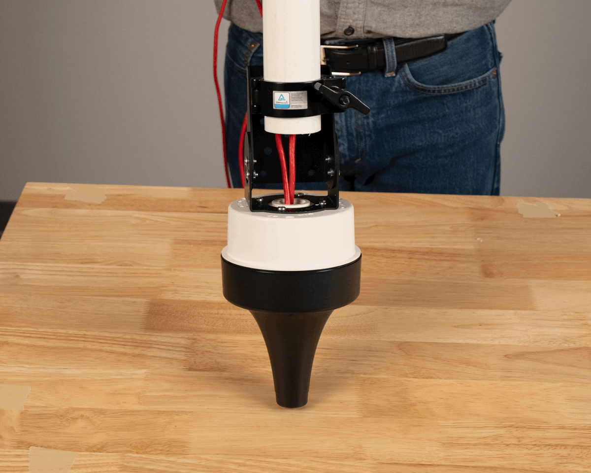
The Articulating Bracket attaches to either the AH301 Flush Mount or the AH302 Box Mount.
Ordering
| Model | Part Number | Description |
|---|---|---|
| AB301 | AB301-K | Articulating Bracket |
| AB302 | AB302-S | Pipe Clamp for Articulating Bracket |
| AB303 | AB303-K | Truss Clamp for Articulating Bracket |
Available from the Ciholas Webshop.
Contents
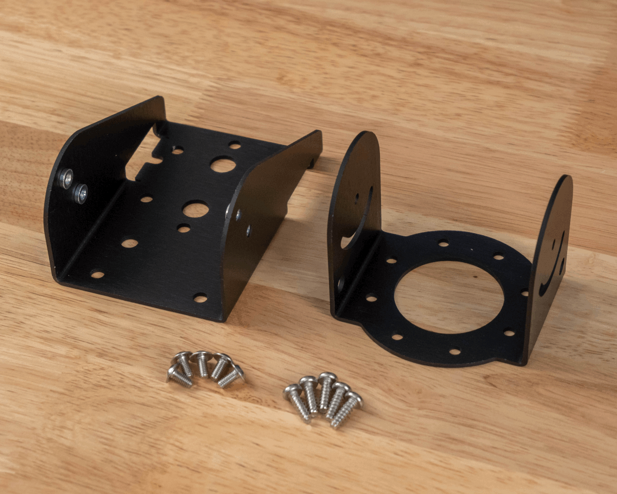
- (1) Articulating Bracket Part A
- (1) Articulating Bracket Part B
- (5) M4 8mm Flanged Head Screws
- (5) #8 1/2” Self Tapping Screws for Plastic
Mechanical
| Parameter | Description | Min. | Typ. | Max | Units |
|---|---|---|---|---|---|
| Unit Mass | Aluminum | 126 | g |
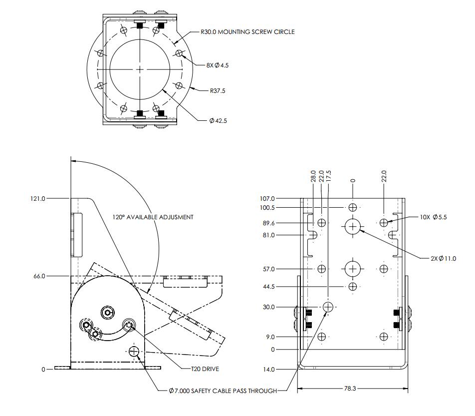
All dimensions are in millimeters unless otherwise stated.
Usage and Application
Intended for deployments where AN302 units need a flexible mounting option. The Articulating Bracket is installed with the AH301 Flush Mount or AH302 Box Mount and can adapt with the following mounting schemes:
- Unistrut, either vertical or horizontal
- V-block pipe clamp
- Truss pipe clamp
- Beam mount
Additional hardware may be required for mounting.
Assembly
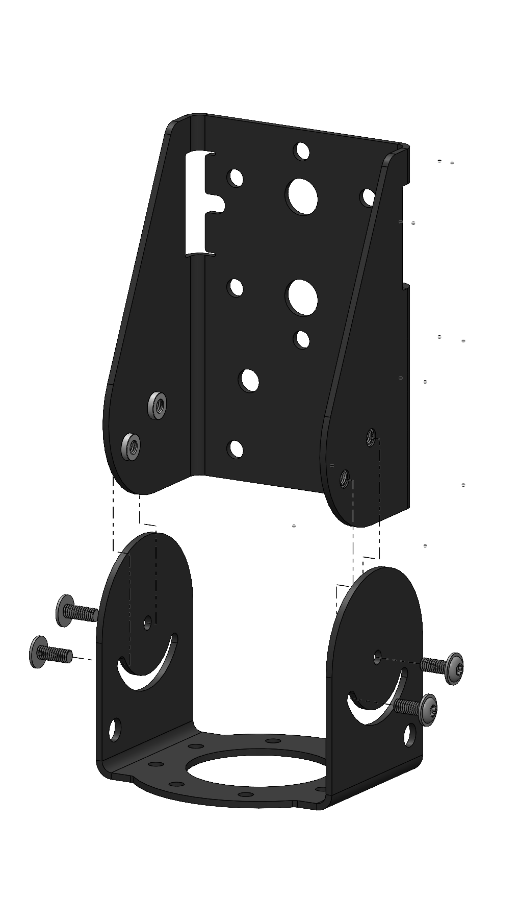
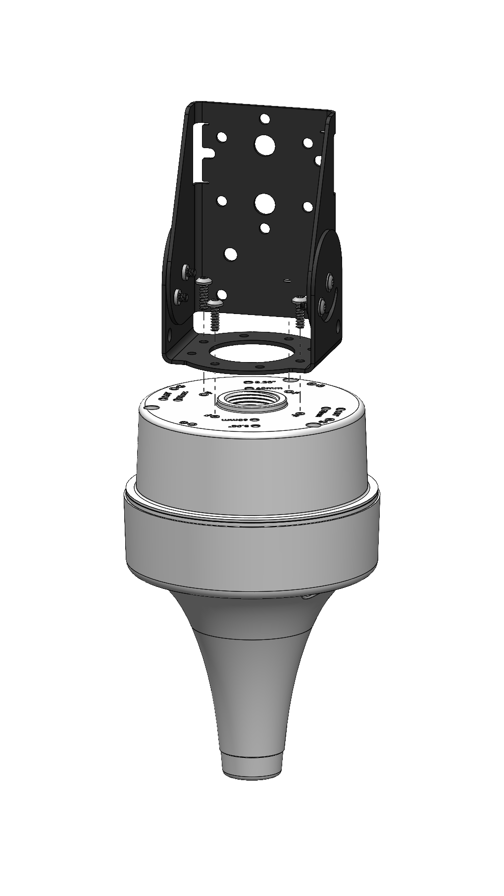
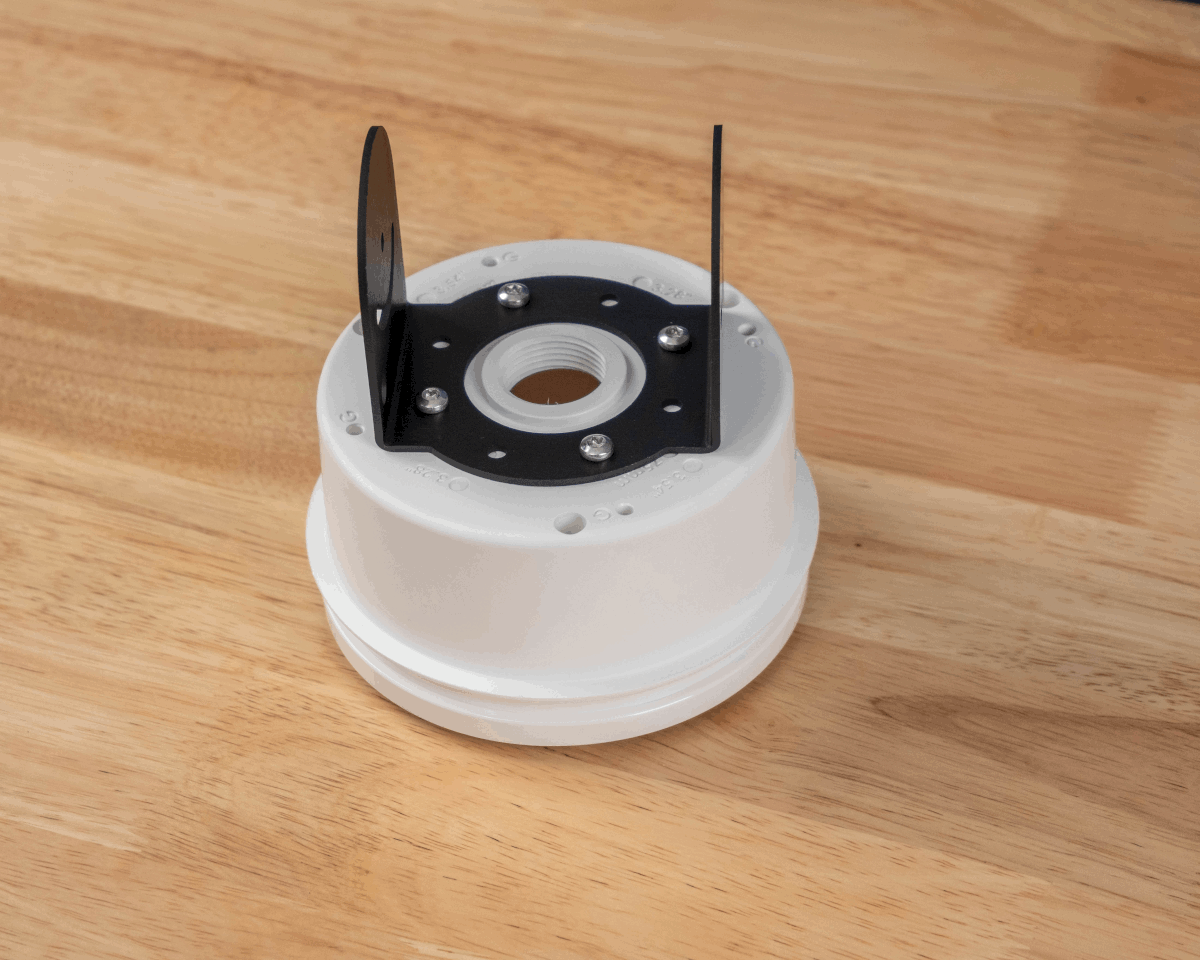
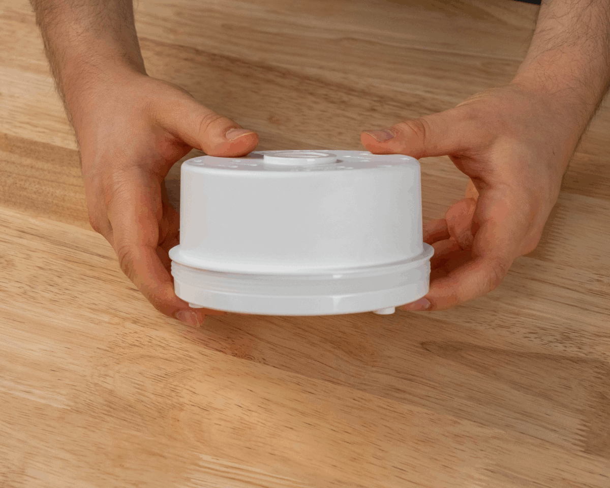
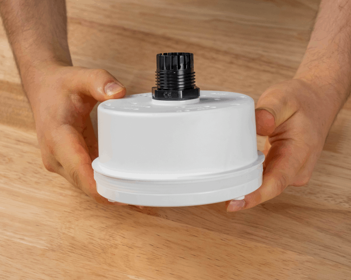
AB301 Parts A & B
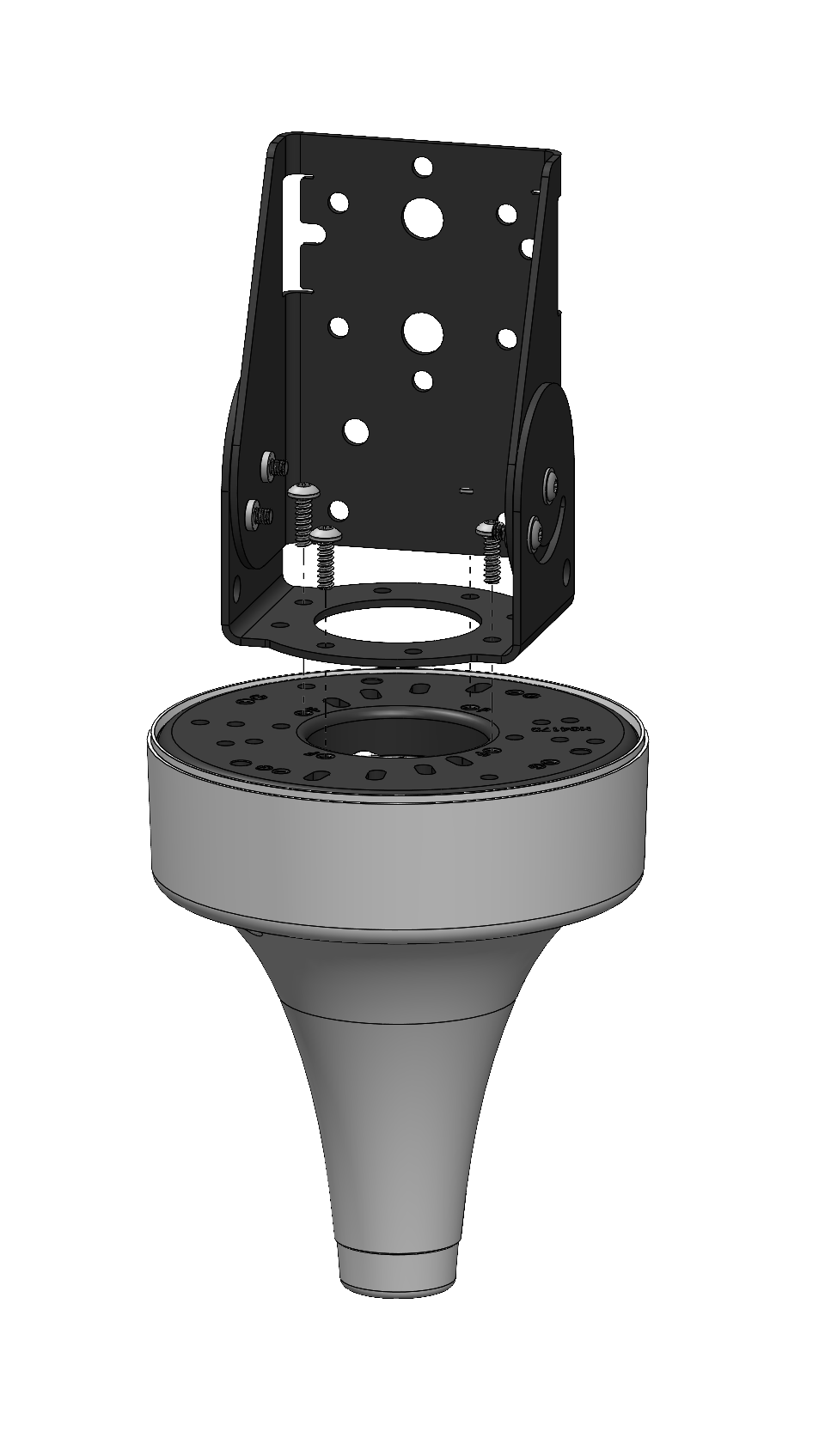
AB301 with AH301 and AH302
 |
 |
|---|---|
| AB301 with AH301 Flush Mount | AB301 with AH302 Box Mount |
Mounting Instructions
AH301
-
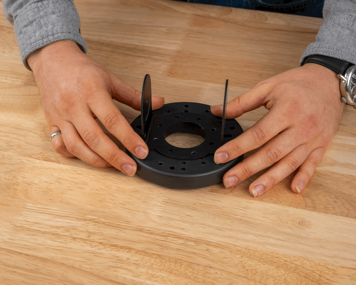
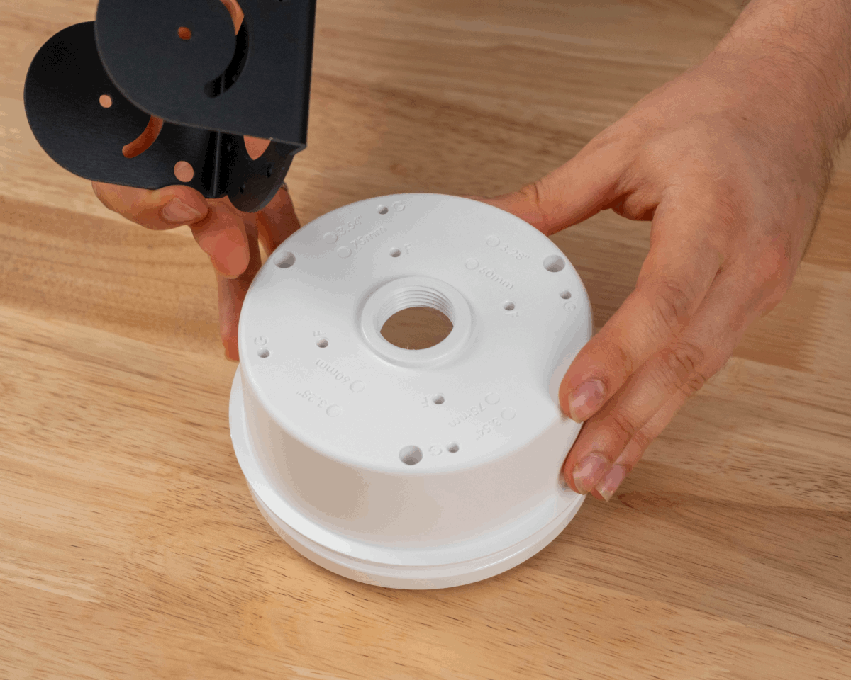
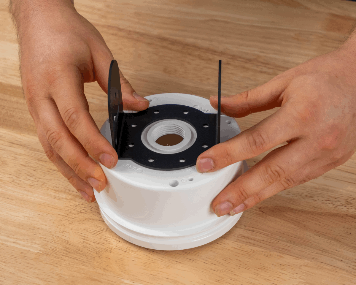
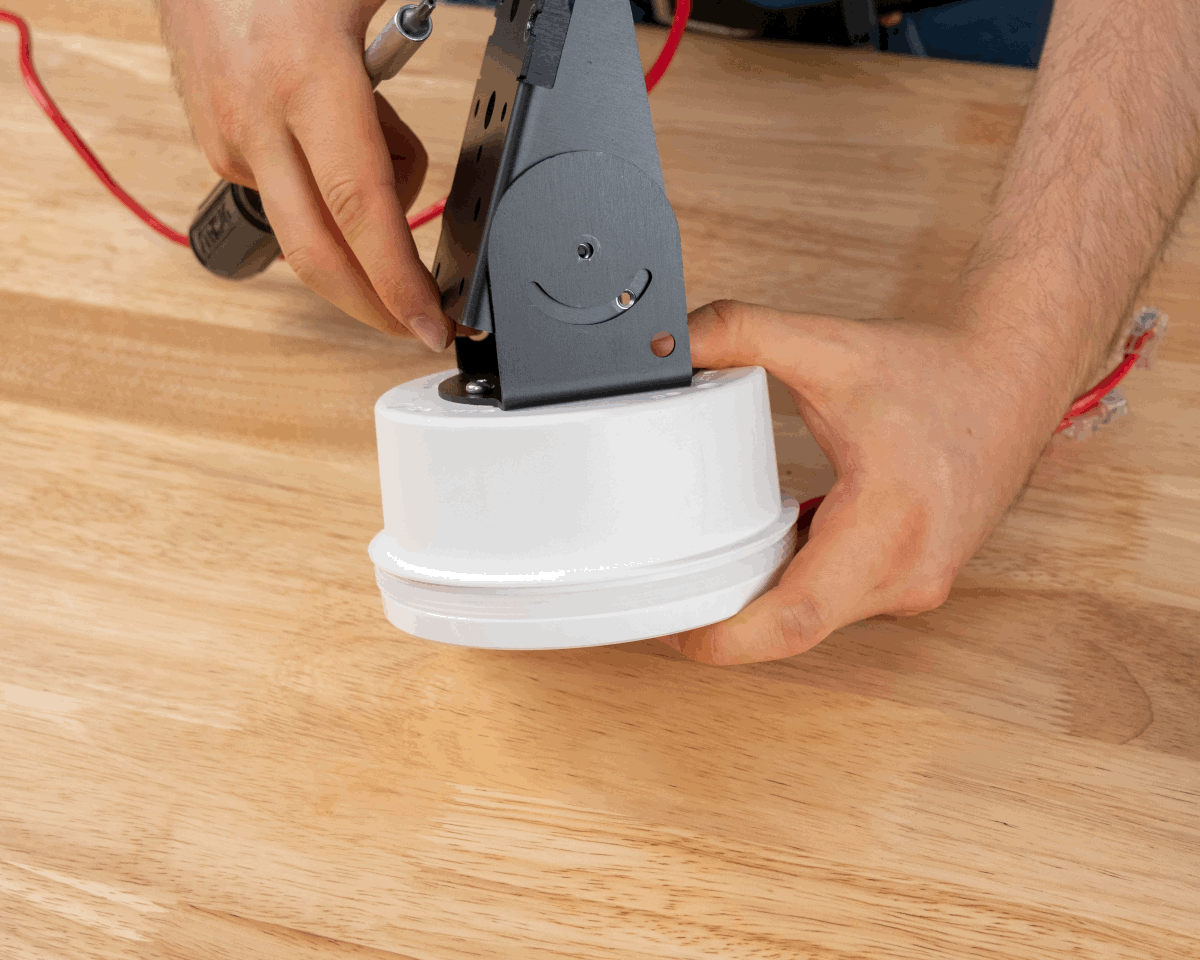
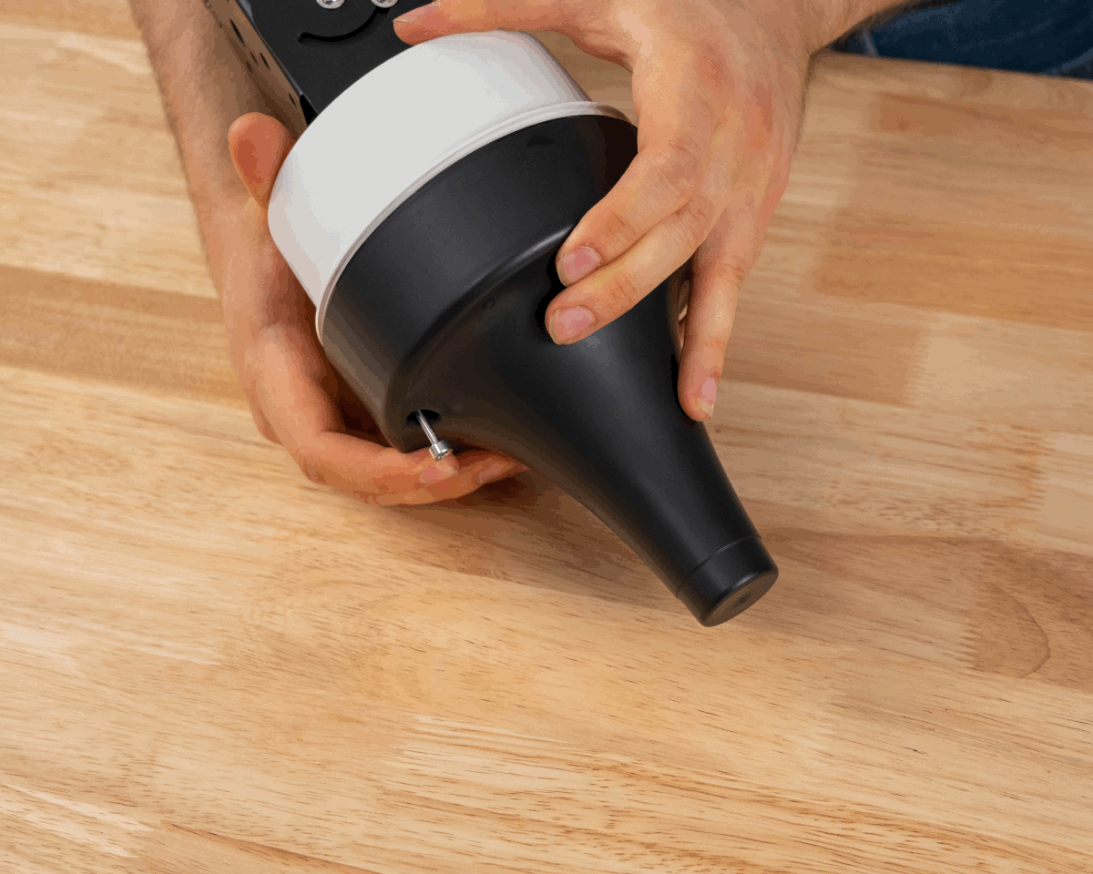
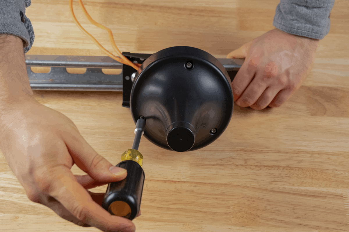
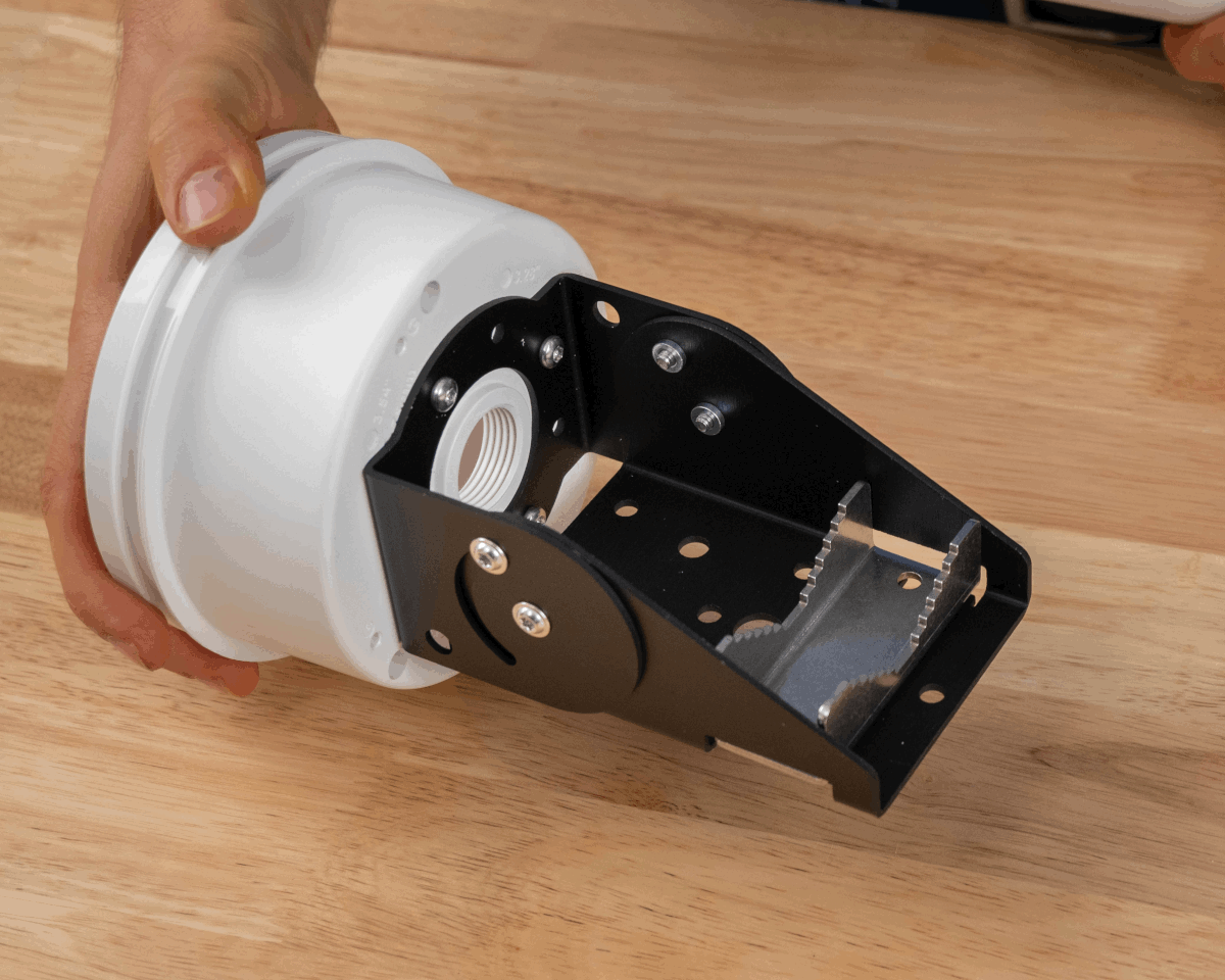
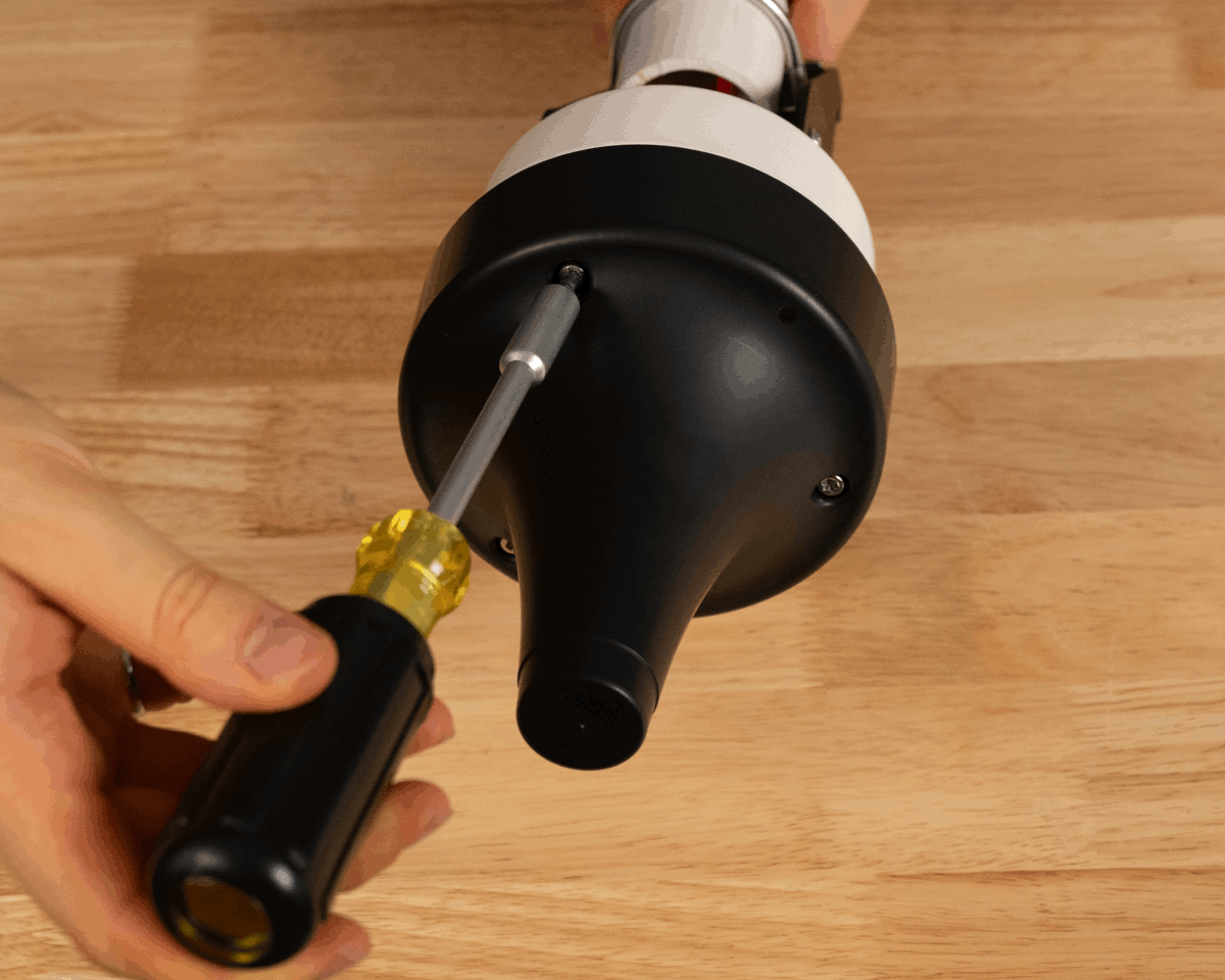
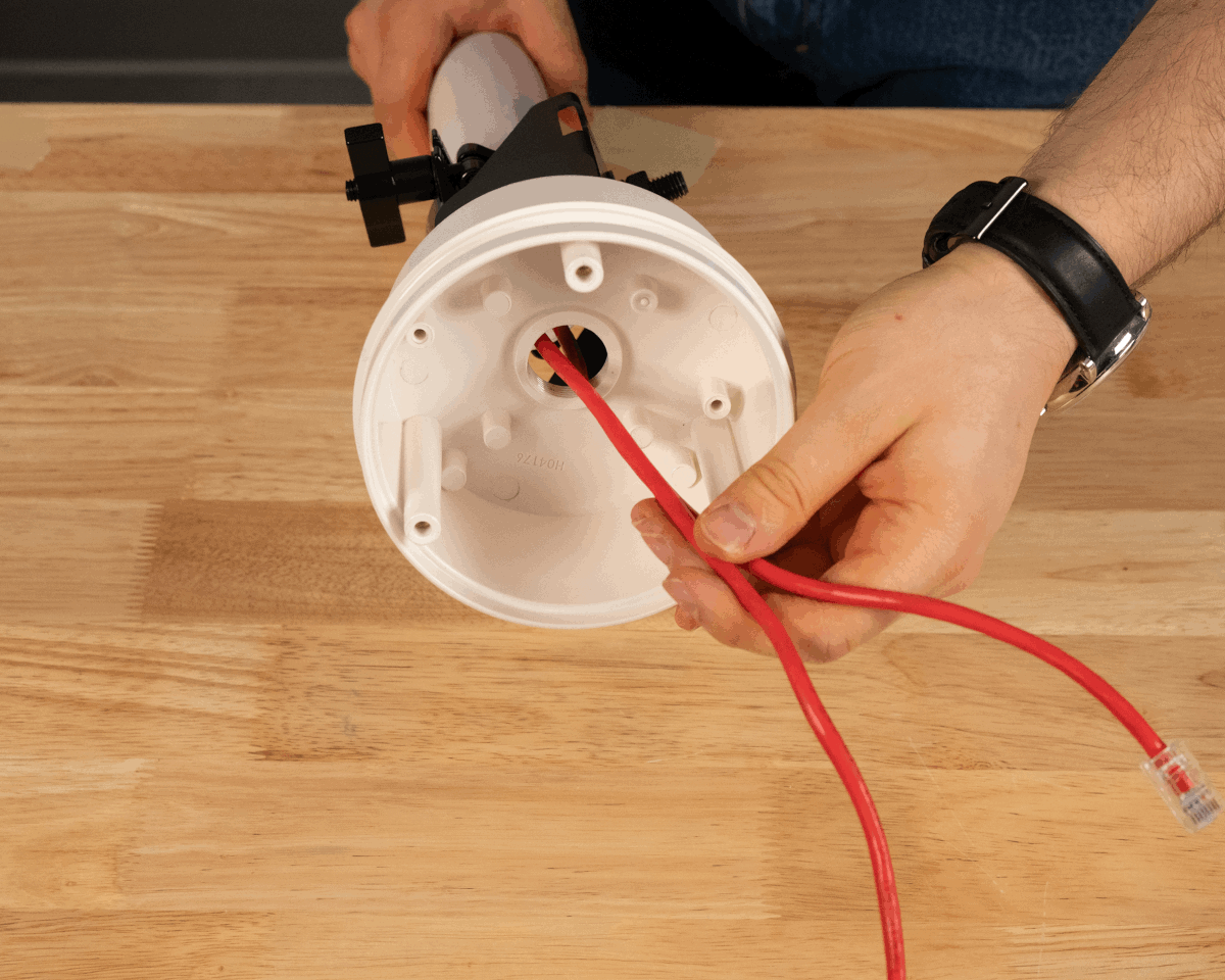
Align AB301 Part B with the F hole pattern on the back of AH301.
-
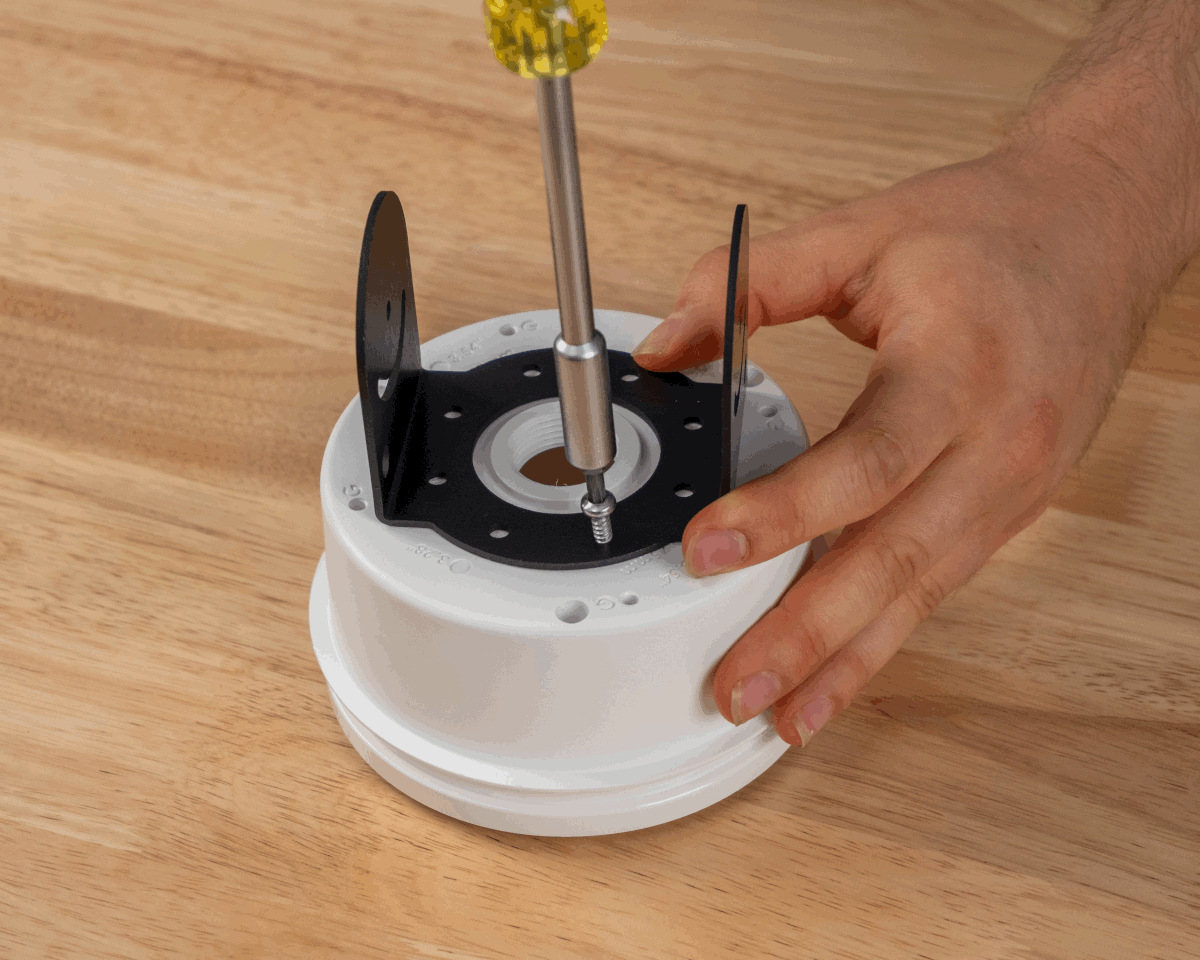
Using the #8 1/2-inch self-tapping screws, attach AB301 Part B to AH301. Use four screws in total; one spare is provided by Ciholas.
Step 1 Step 2 -
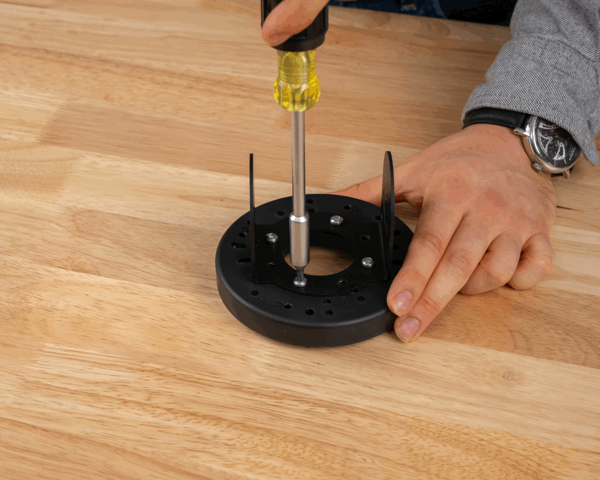
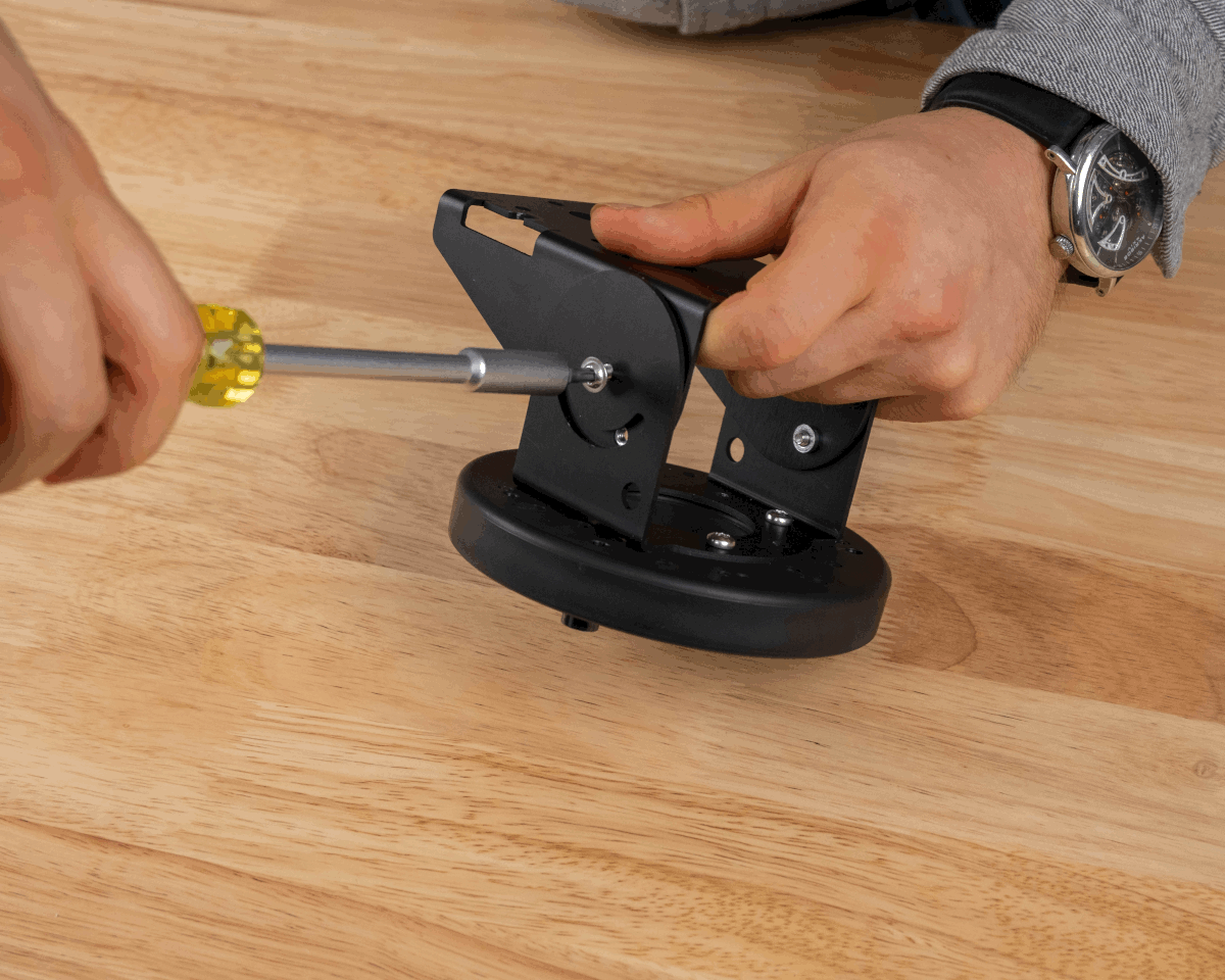
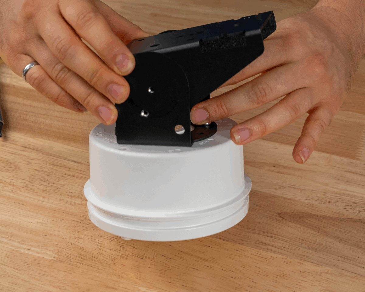
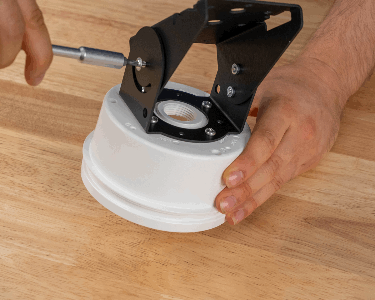
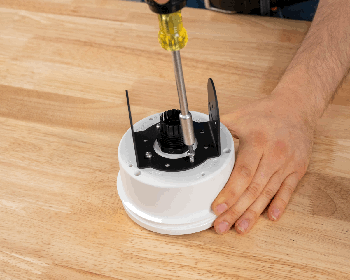
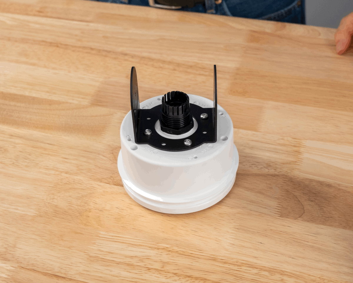
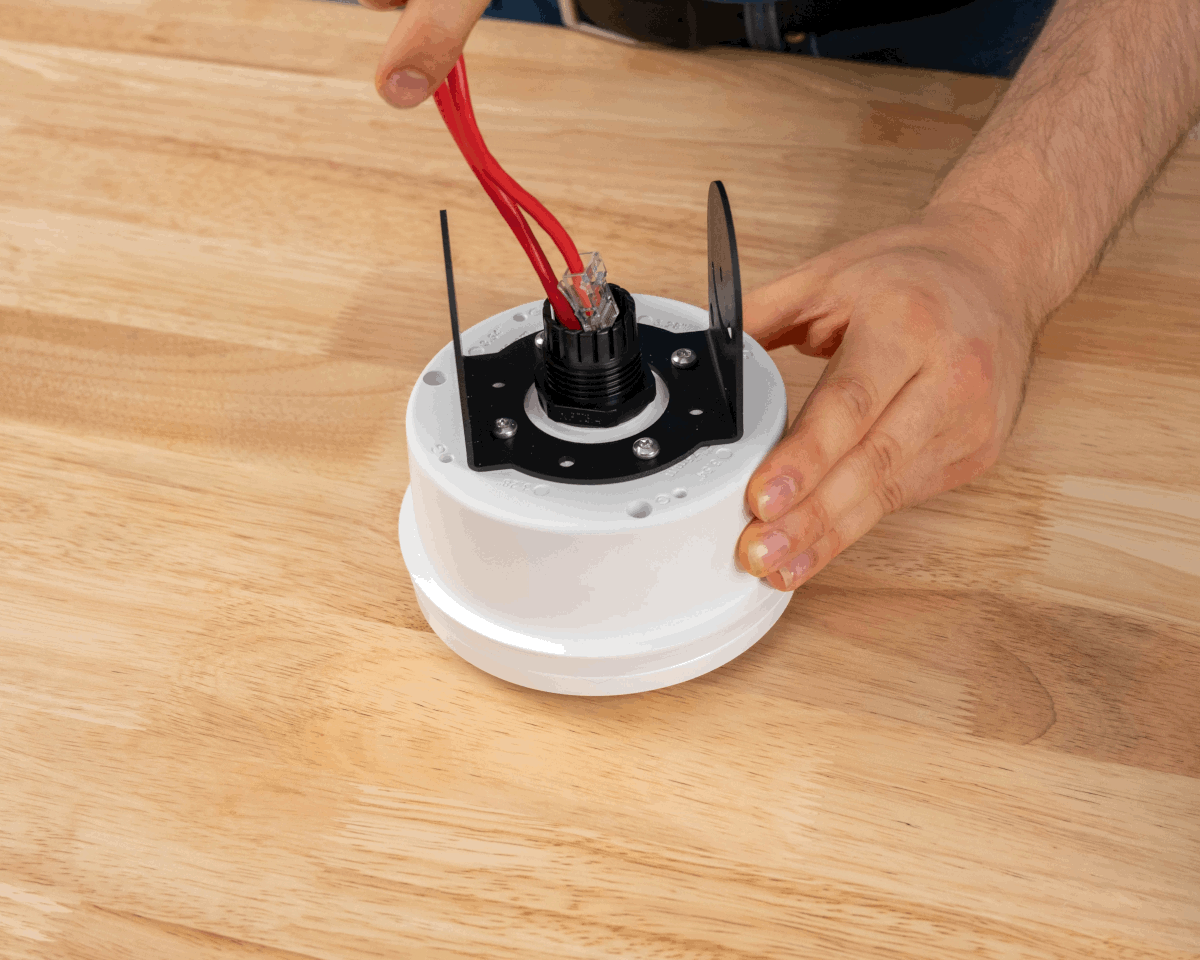
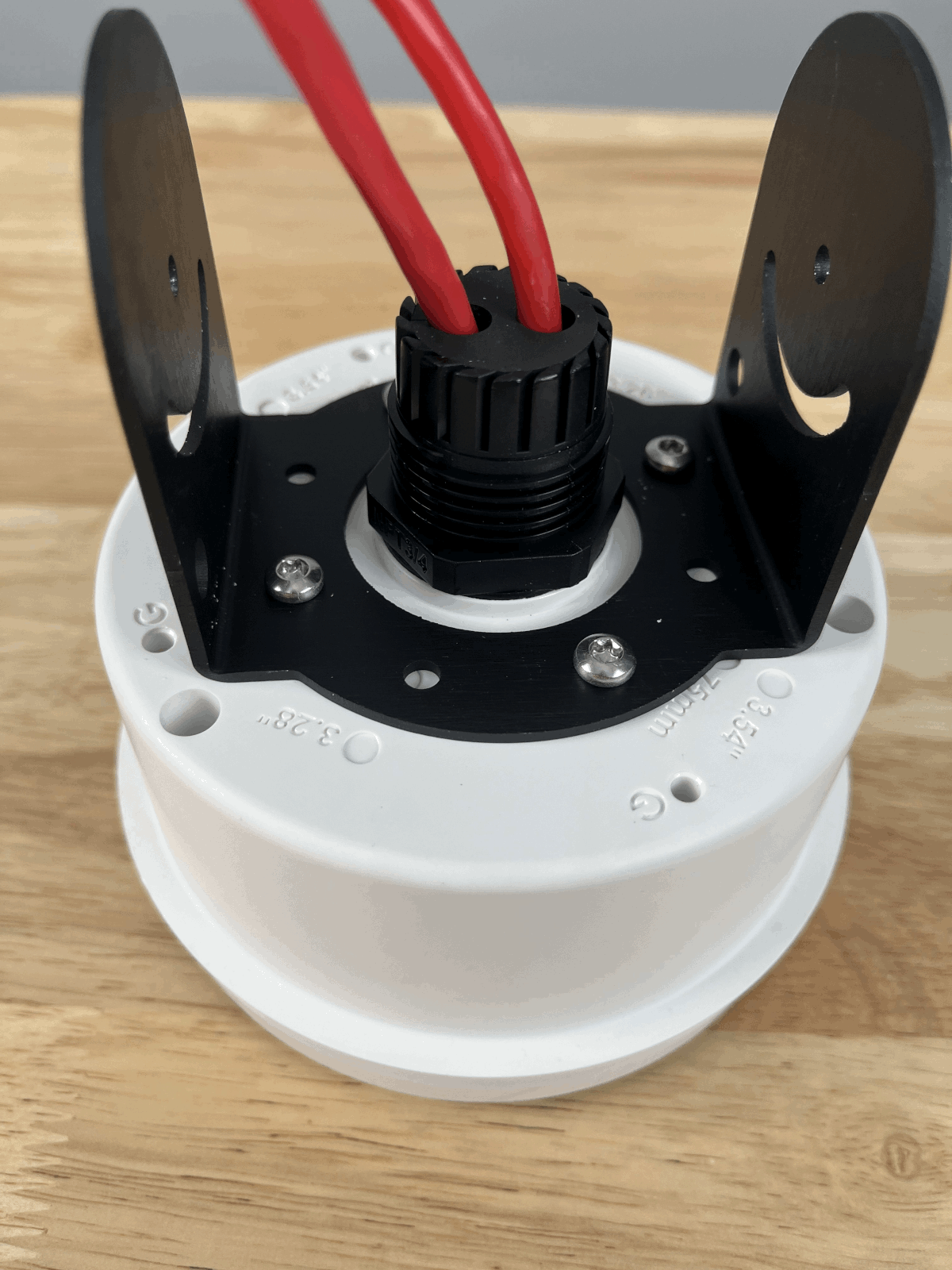
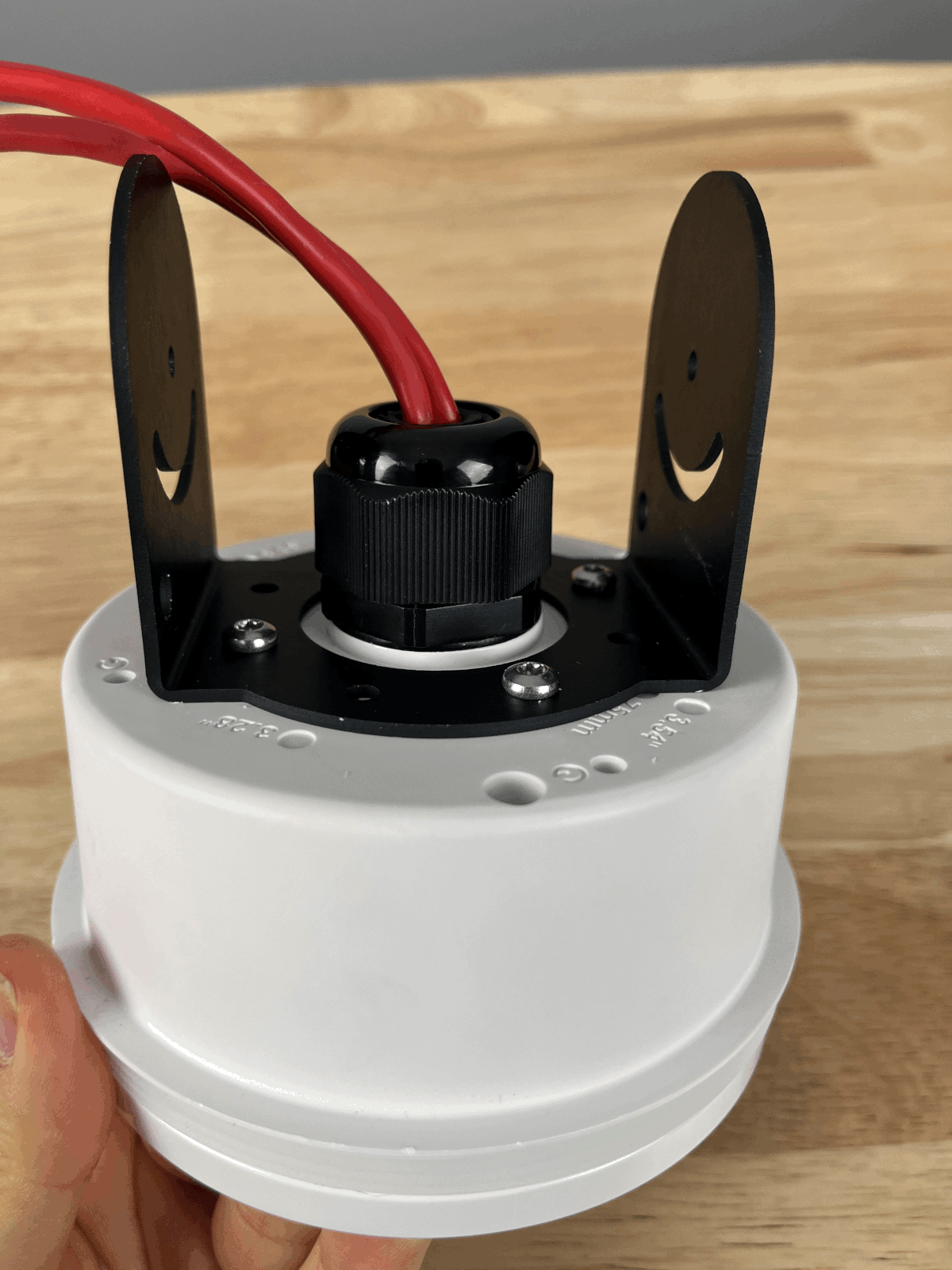
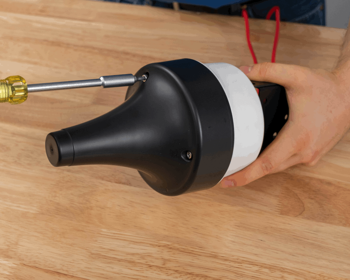
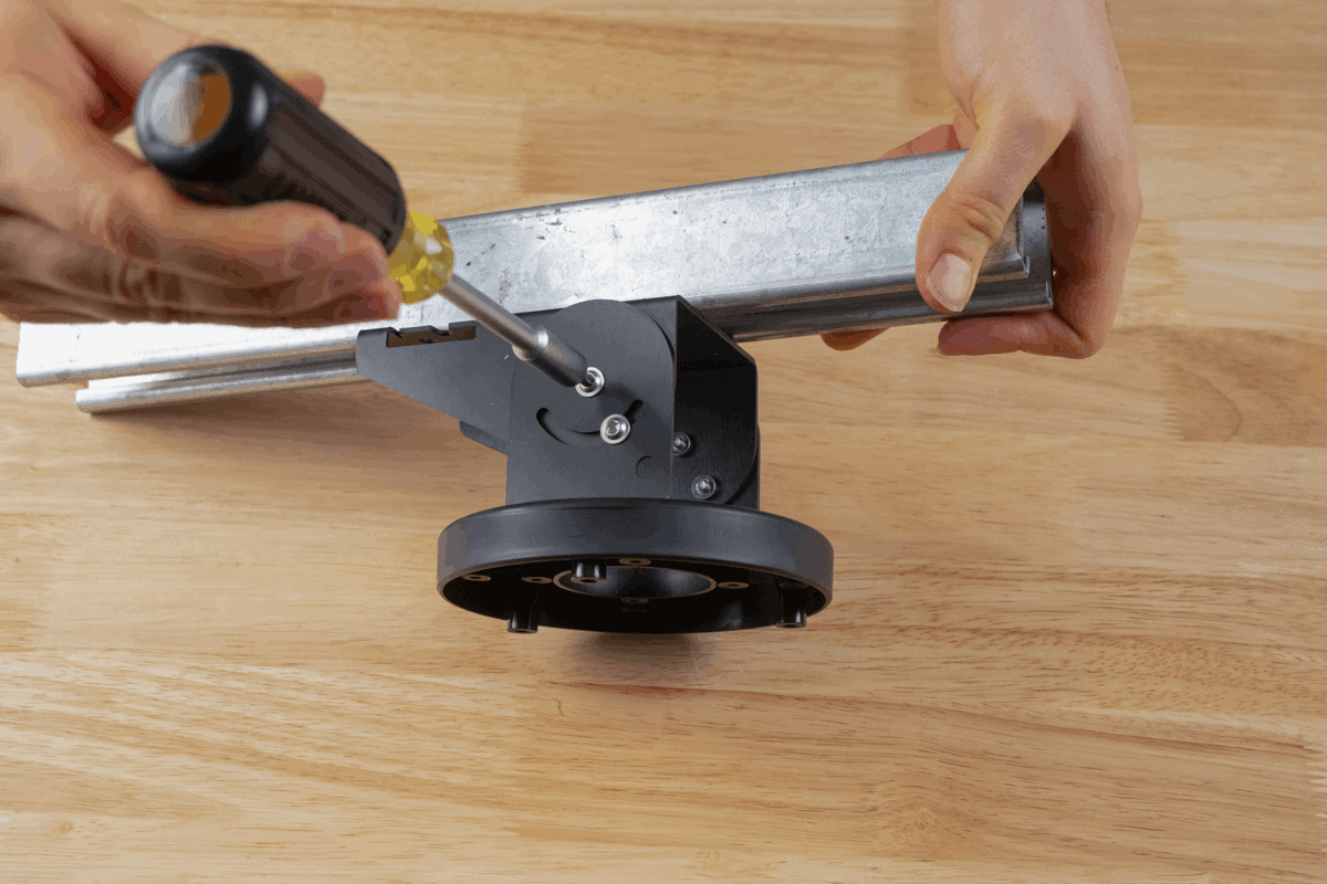
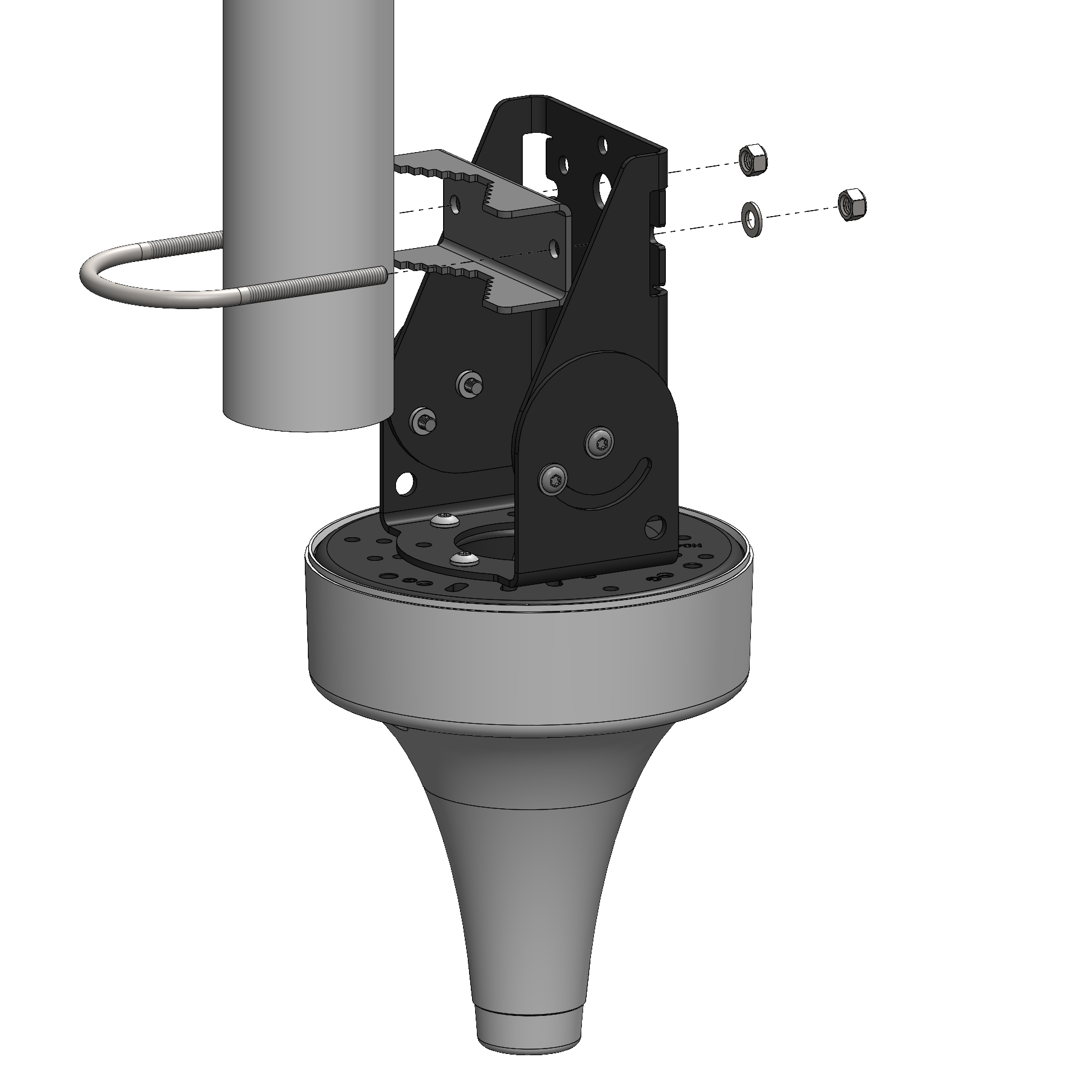
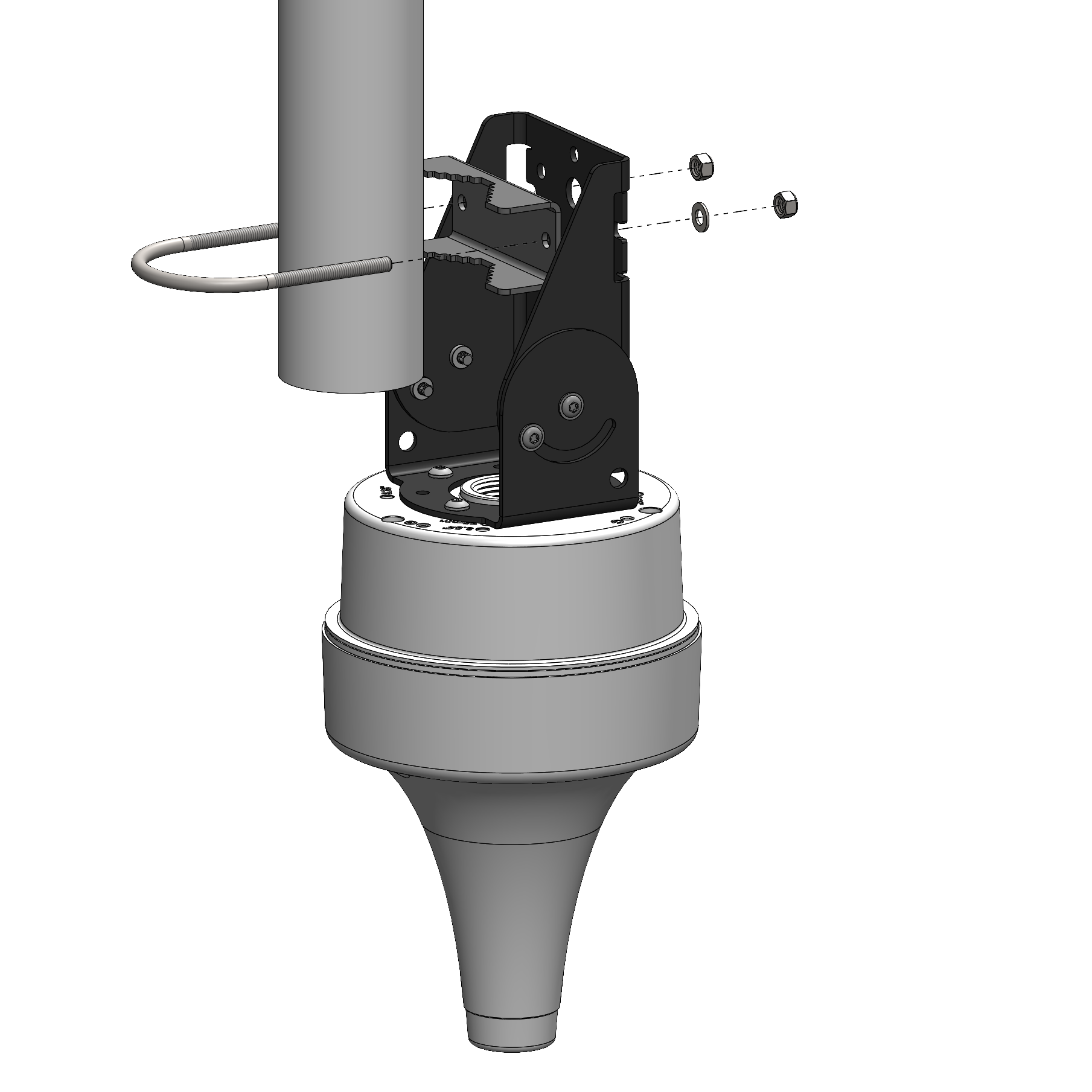
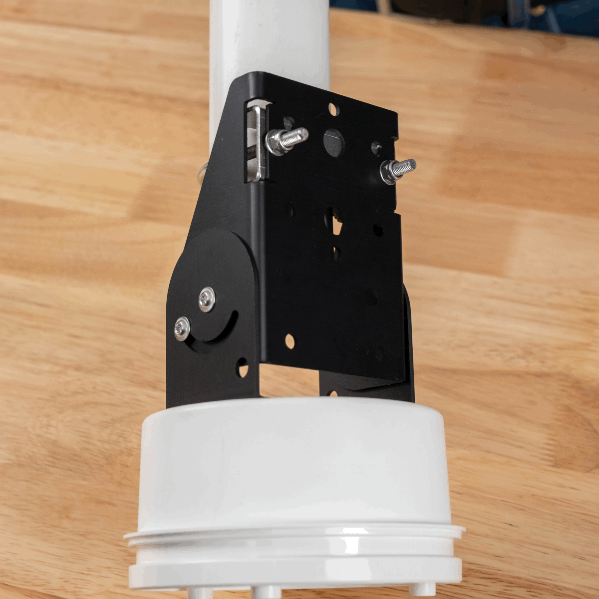
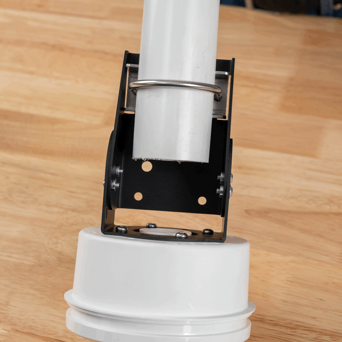
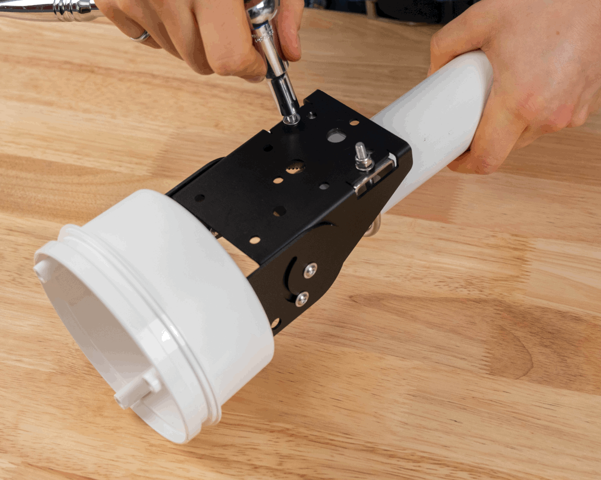
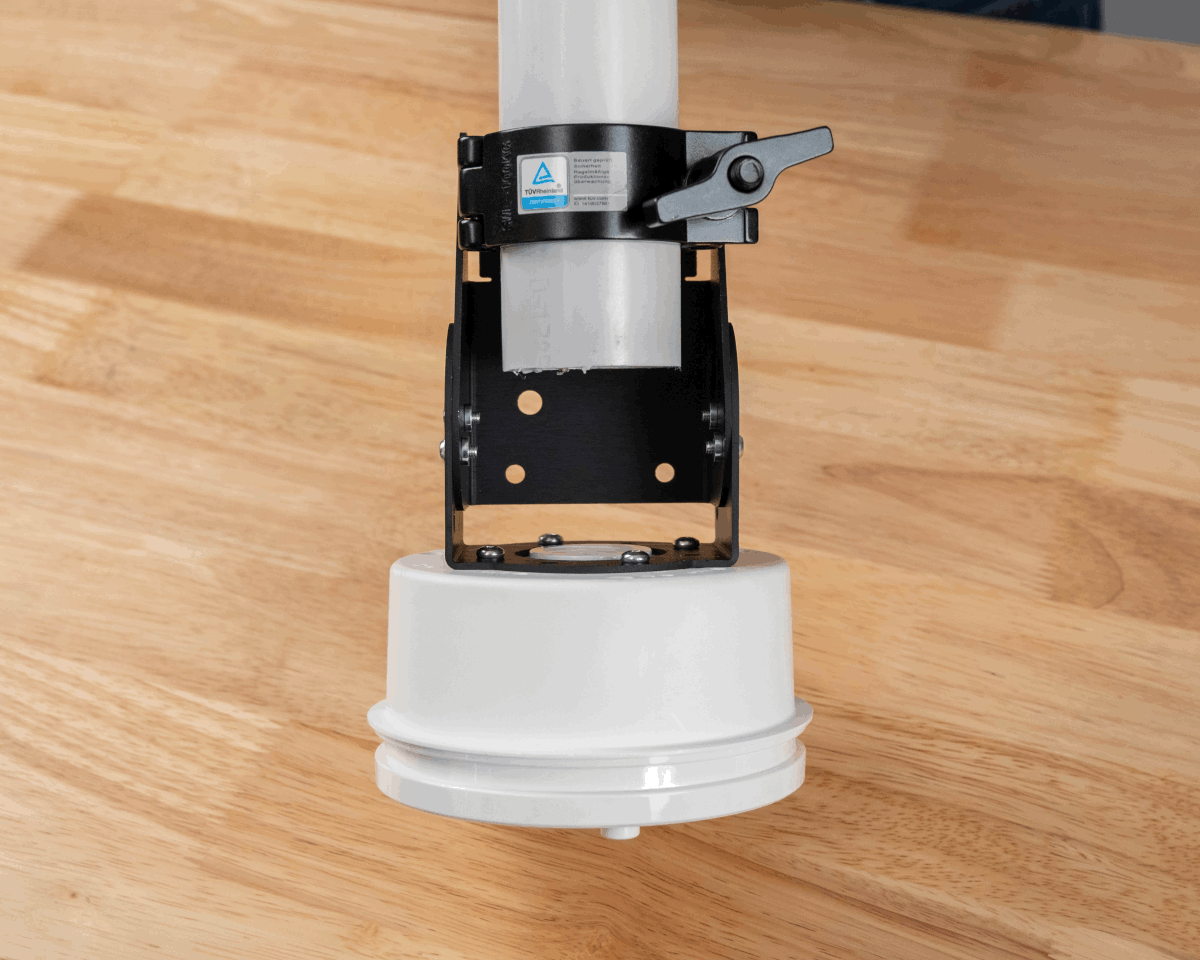
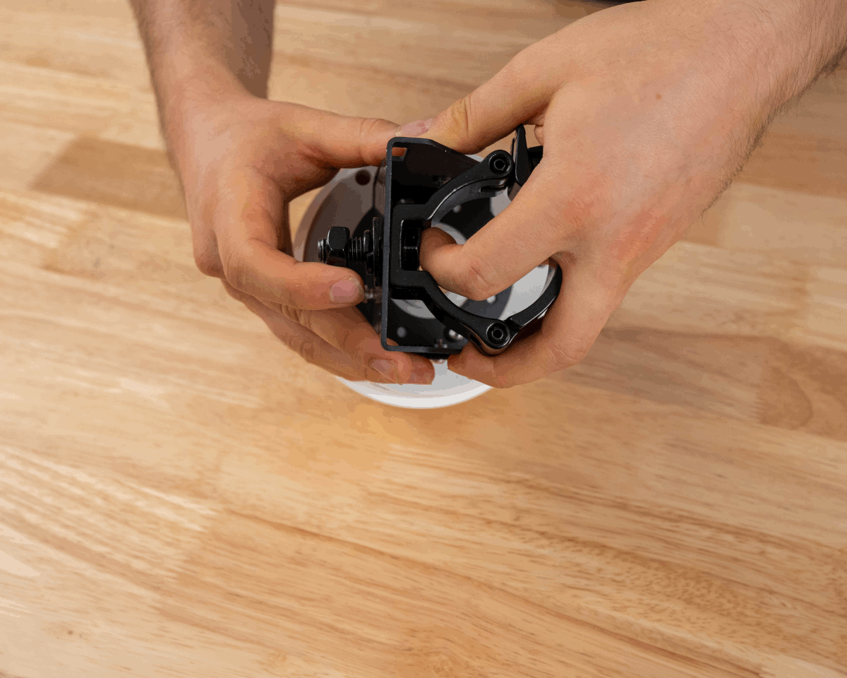
Align the assembly holes in Part B of AB301 with the threaded inserts in Part A.
-
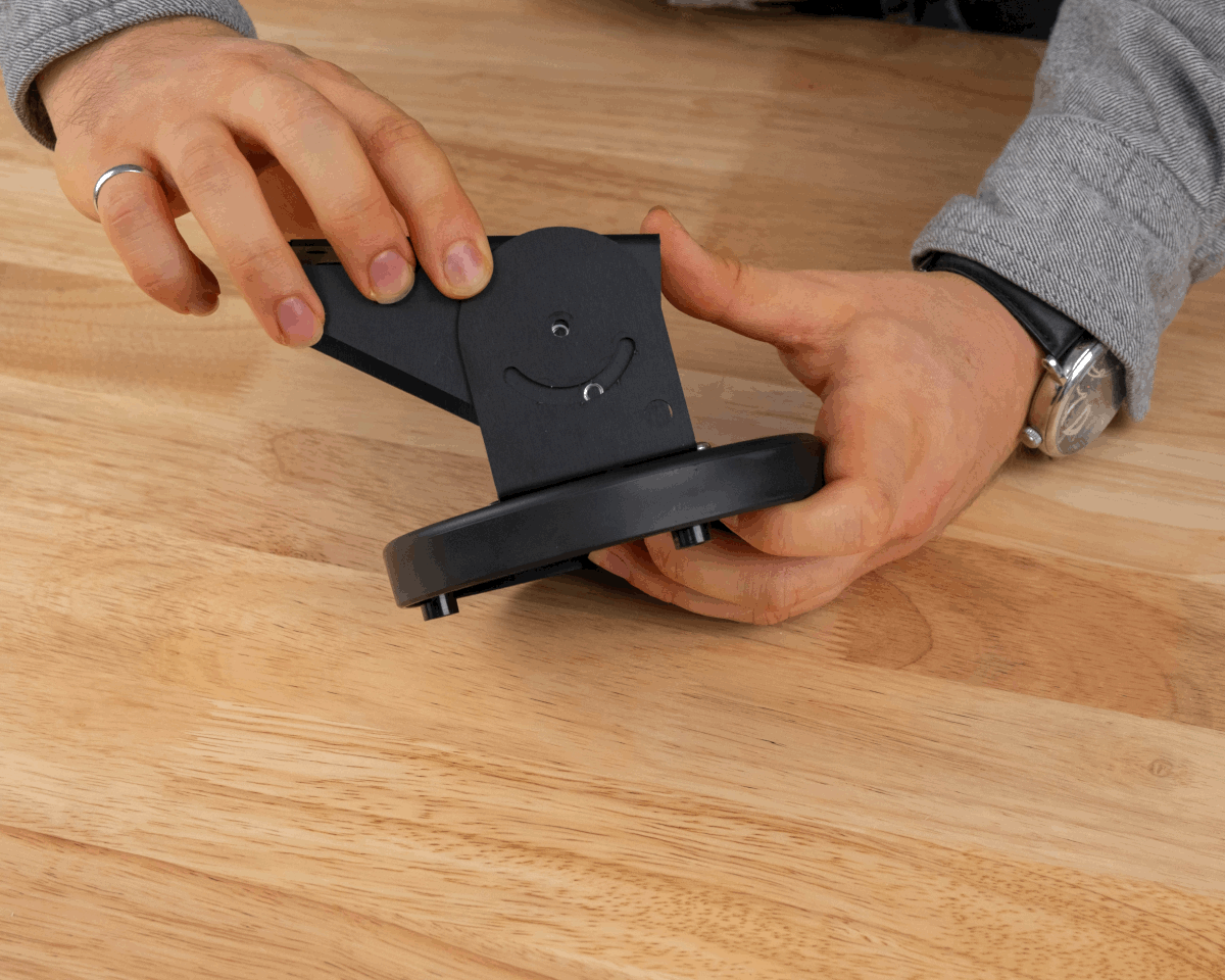
Using the M4 8mm flanged-head screws, attach AB301 Part A to AB301 Part B. One spare screw is provided by Ciholas. Adjust the required angle for the bracket as needed.
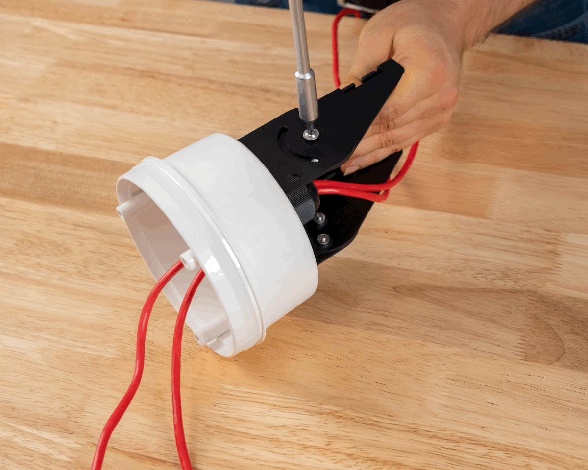
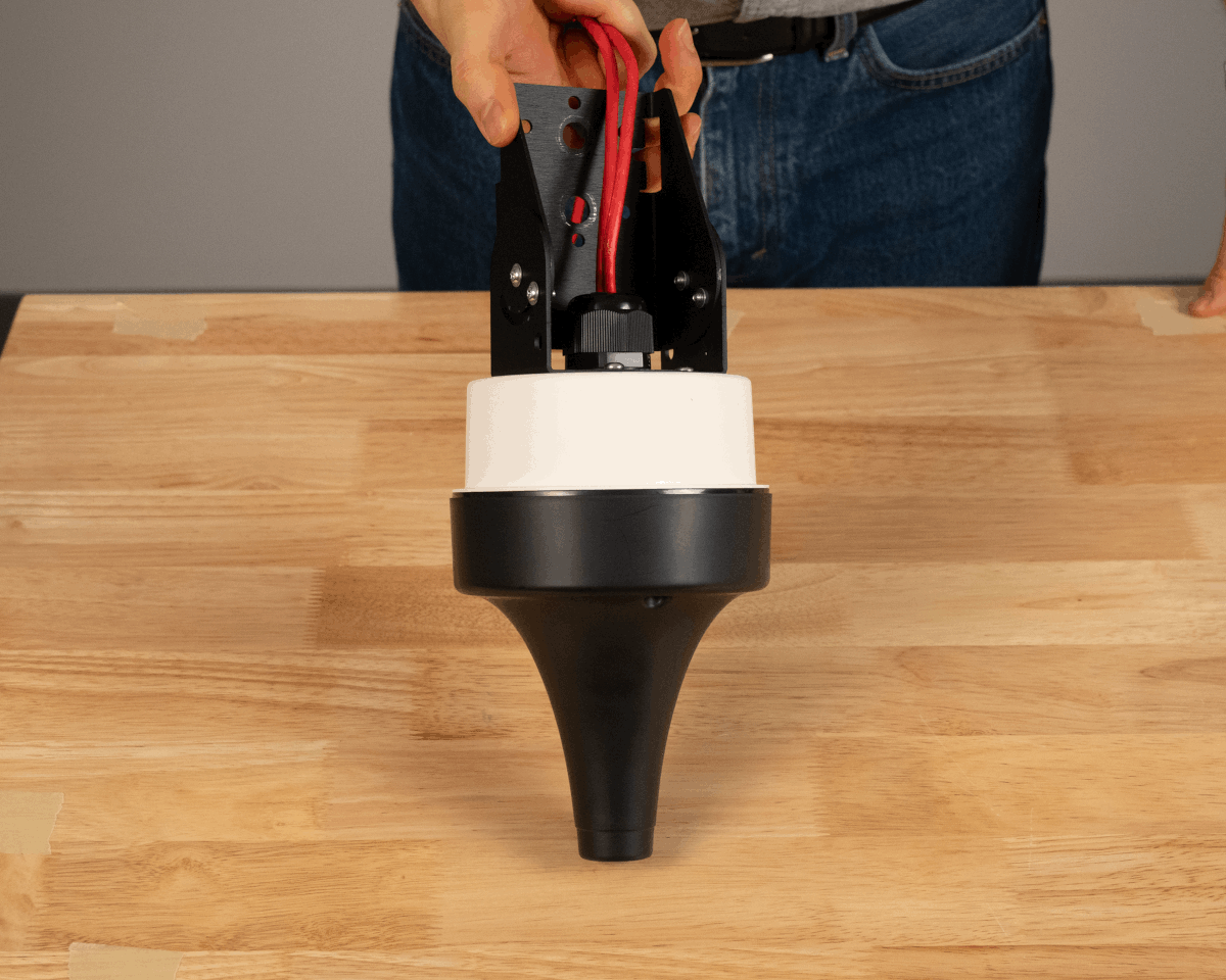
Step 3 Step 4 - Install AB301 to mounting location directly or with AB302 or AB303 accessories.
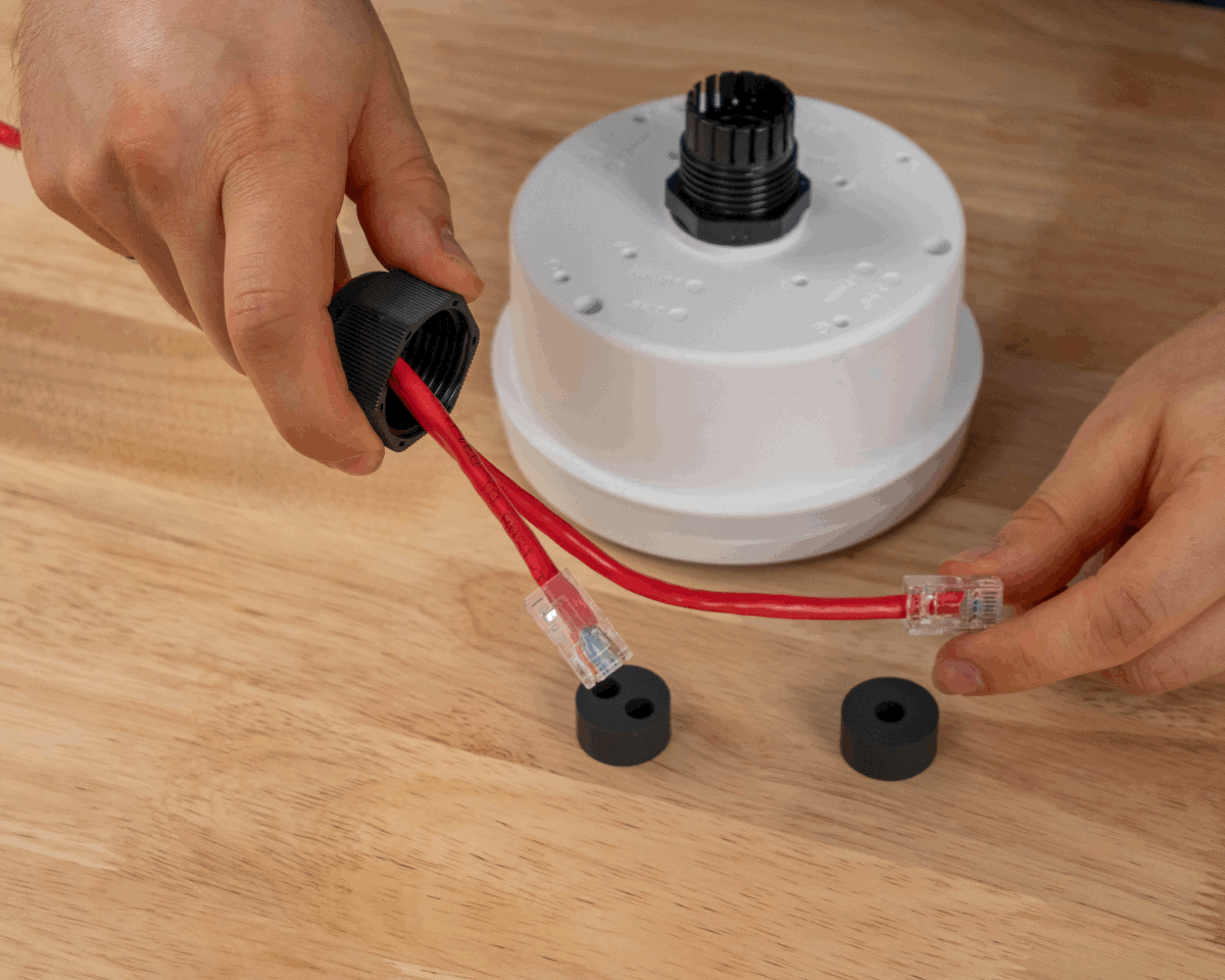
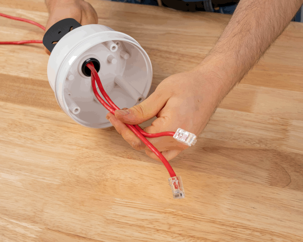
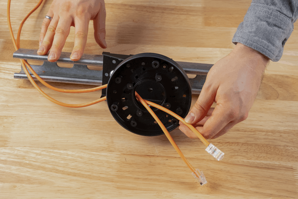
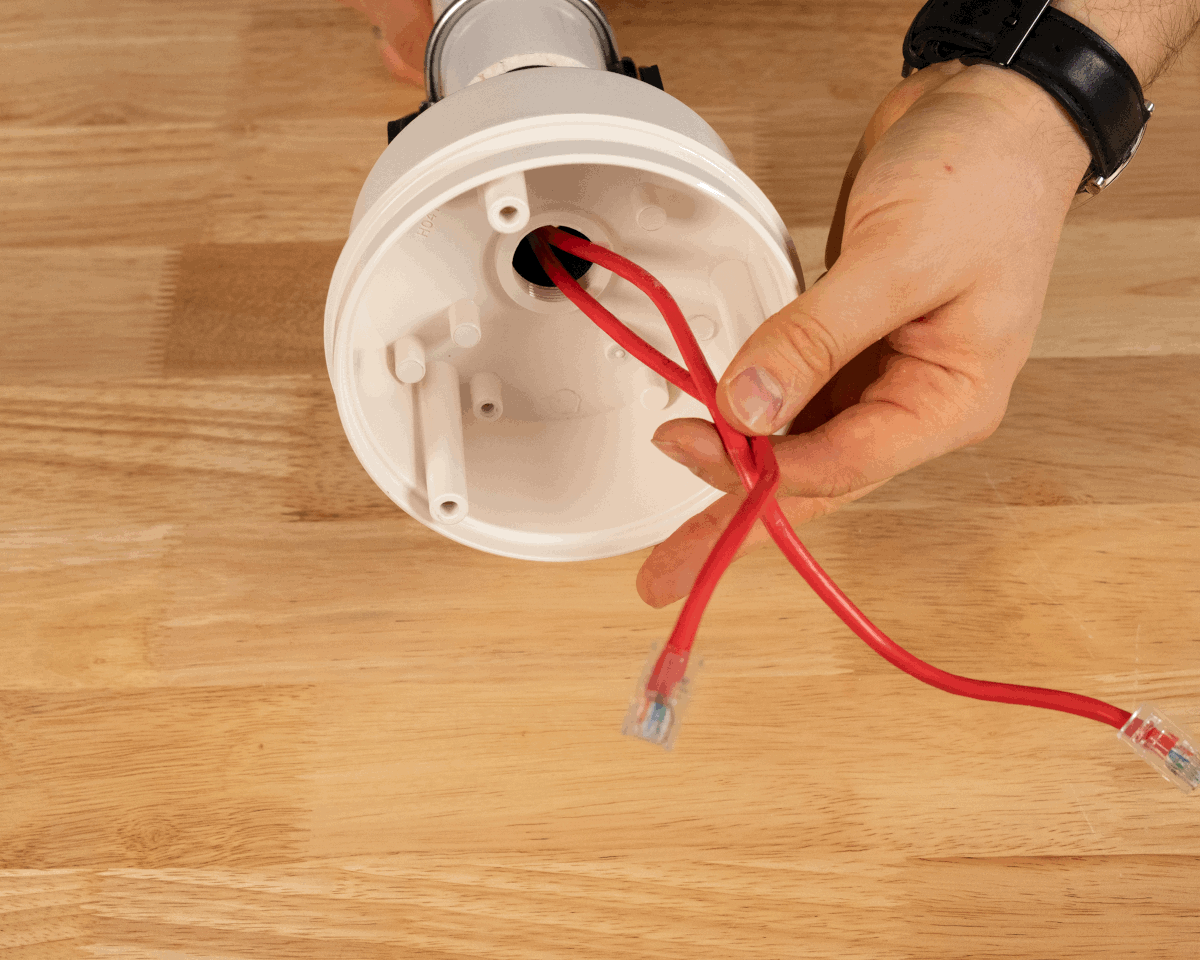
- Route cables through the mount.
- Provide enough cable for a service loop and plug in cable(s).
- Install AN302 to AH301 using the captive screws. Use a T20 drive set to 0.68 N-m (6 in-lb) of torque.
AH302
-
Align AB301 Part B with the F hole pattern on the back of AH302.
Step 1a Step 1b -
Using the #8 1/2-inch self-tapping screws, attach AB301 Part B to AH302. Use four screws in total; one spare is provided by Ciholas.
Step 2a Step 2b -
Align the assembly holes in Part B of AB301 with the threaded inserts in Part A.
-
Using the M4 8mm flanged-head screws, attach AB301 Part A to AB301 Part B. One spare screw is provided by Ciholas. Adjust the required angle for the bracket as needed.
Step 3 Step 4 - Install AB301 to mounting location directly or with AB302 or AB303 accessories.
- Route cables through the mount.
- Provide enough cable for a service loop and plug in cable(s).
- Install AN302 to AH302 using the captive screws. Use a T20 drive set to 0.68 N-m (6 in-lb) of torque.
AH302 with AH303 Sealing Kit
-
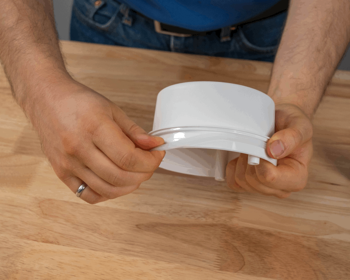
Insert the sealing gasket into the groove of the AH302 Box Mount with the large “teeth” facing outwards. Verify the seal is stretched evenly.
Step 1 View of gasket -
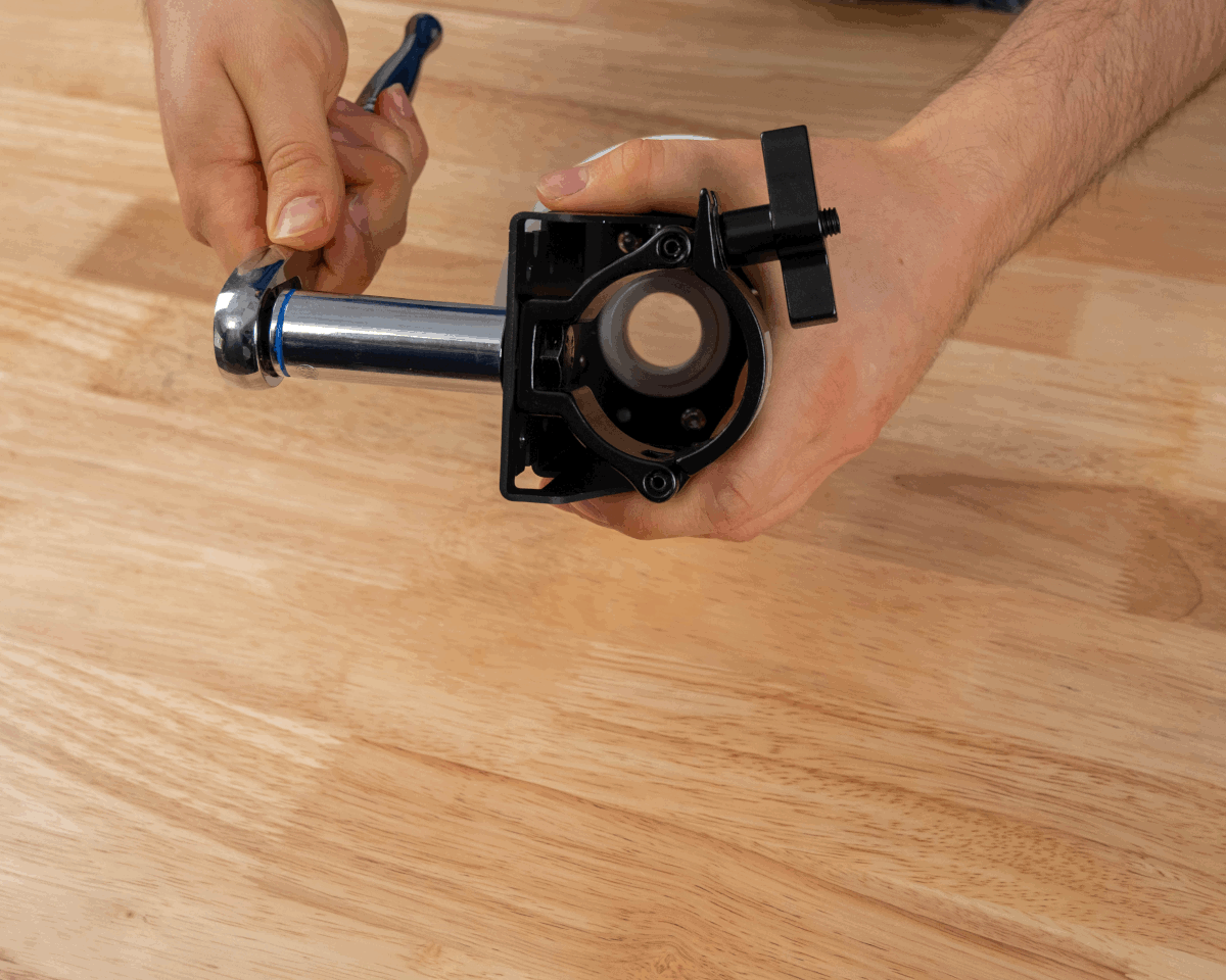
Unscrew the cap and hex nut from the 3/4-inch NPT cable gland. The hex nut will not be used.
-
Remove the pre-installed rubber cable seal from the cable gland.
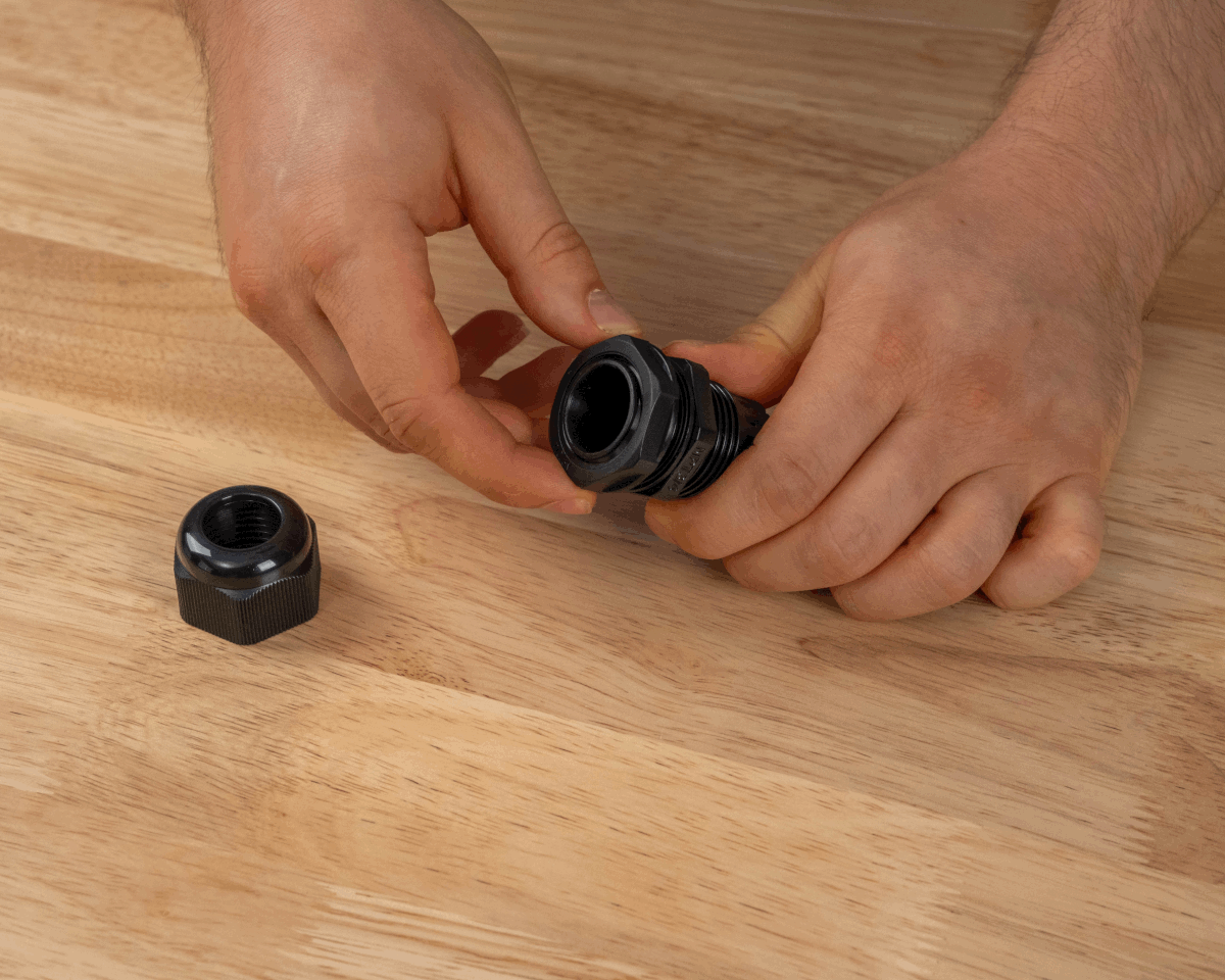
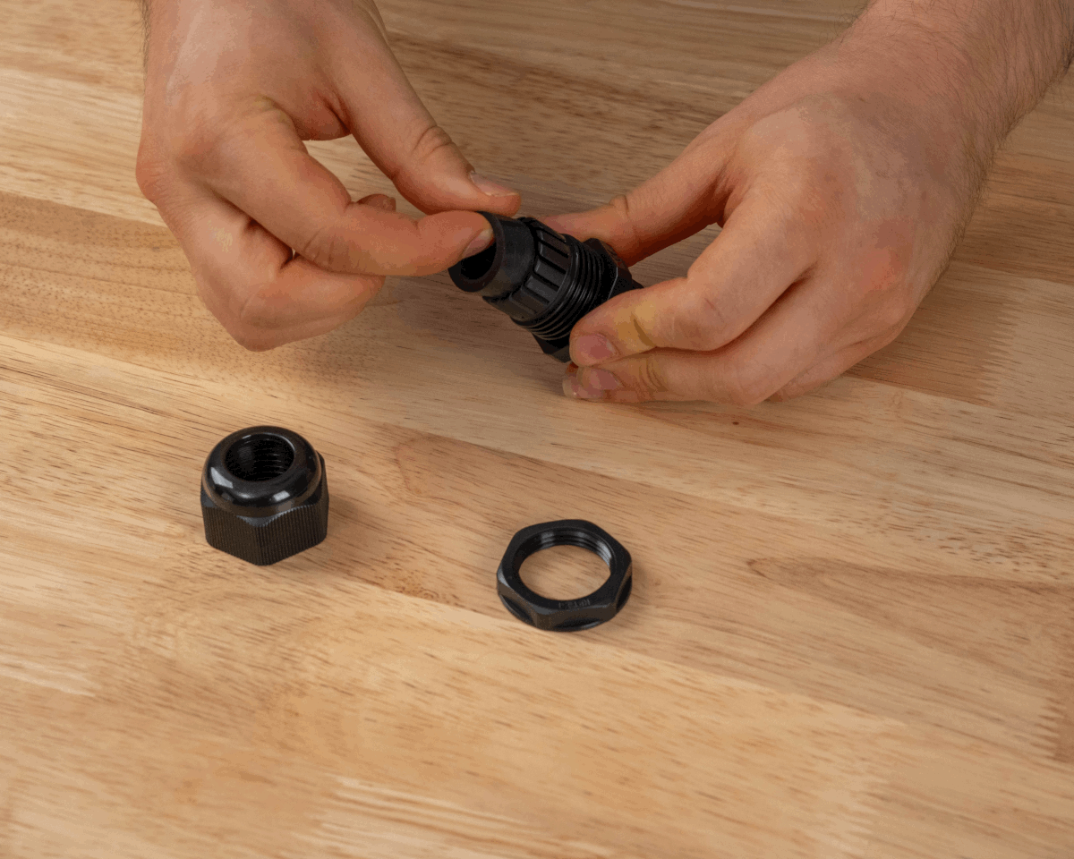
Step 2 Step 3 -
Screw the end of the cable gland to the AH302 Box Mount. Fully seat the flat rubber gasket onto the plastic and tighten to create a seal.
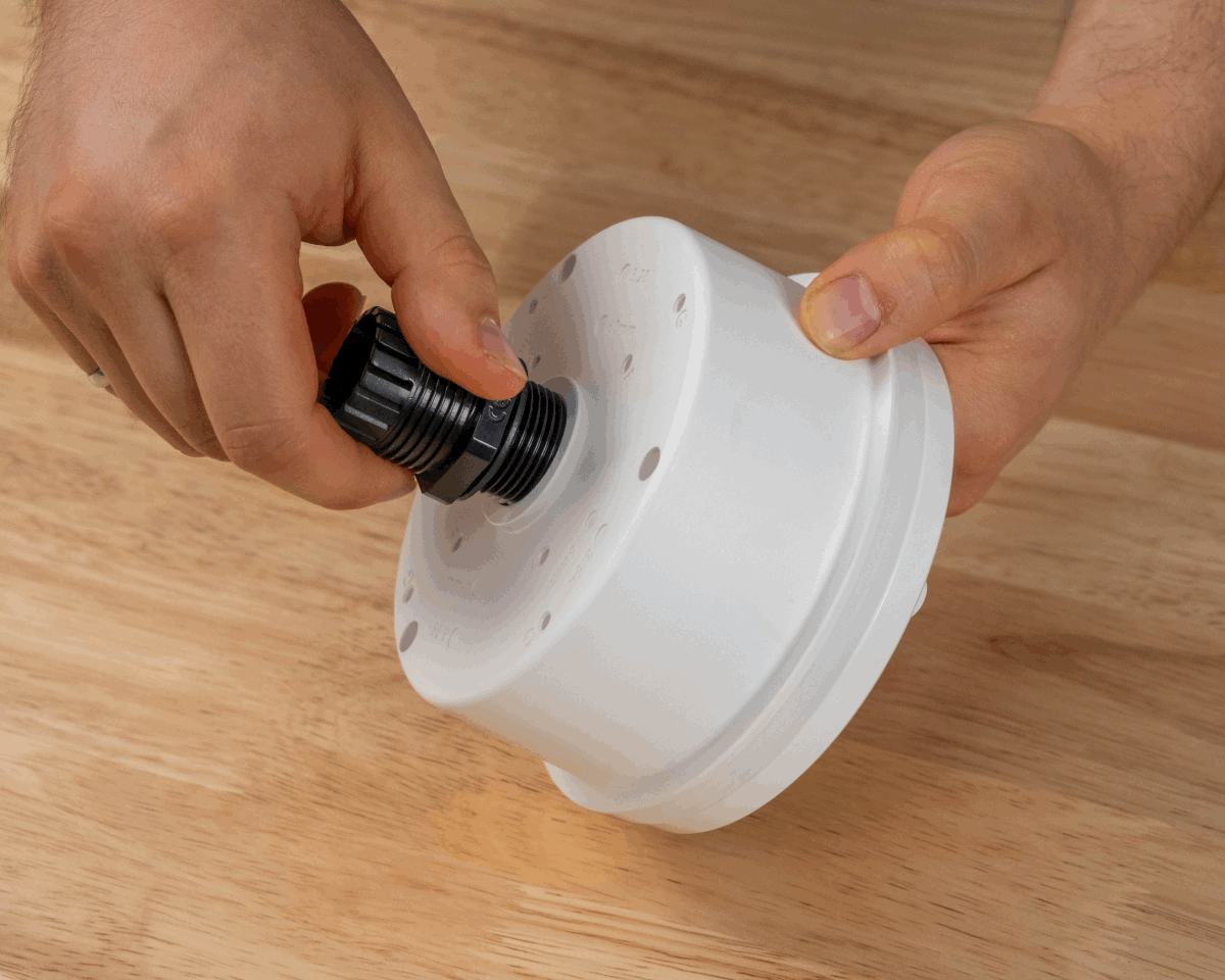
Step 4 View of cable gland fully seated - Align AB301 Part B with the F hole pattern on the back of the AH302.
-
Using the #8 1/2-inch self-tapping screws, attach AB301 Part B to AH302. Use four screws in total; one spare is provided by Ciholas.
Step 5 Step 6 -
Insert 1 (or 2) Ethernet cable(s) through the cap nut of the cable gland.
-
Select either the Single cable insert or the dual cable insert for the cable gland. Insert the Ethernet cable(s) through the slit(s) in the seal. The ring of silicon on the seal should face away from the cap nut.

Step 7 Step 8 -
Insert the cables through the gland and AH302 from the exterior. Provide enough cable for a service loop to allow the anchor to be removed and disconnected once the cables are sealed with the gland.
Step 9 View of cable for service loop -
Fully seat the cable insert into the gland. The top of the seal should be flush with the top of the gland. Screw the cap nut onto the cable gland and tighten.
View of seal flush with the gland Step 10 -
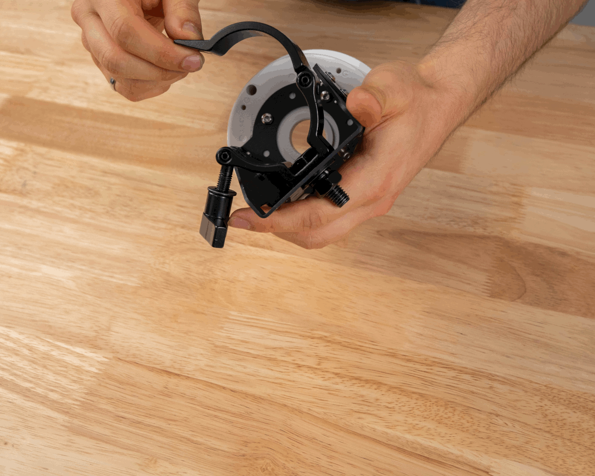
Align AB301 Part A with Part B.
-
Using the M4 8mm flanged-head screws, attach AB301 Part A to AB301 Part B. Adjust the required angle for the bracket as needed.
Step 11 Step 12 -
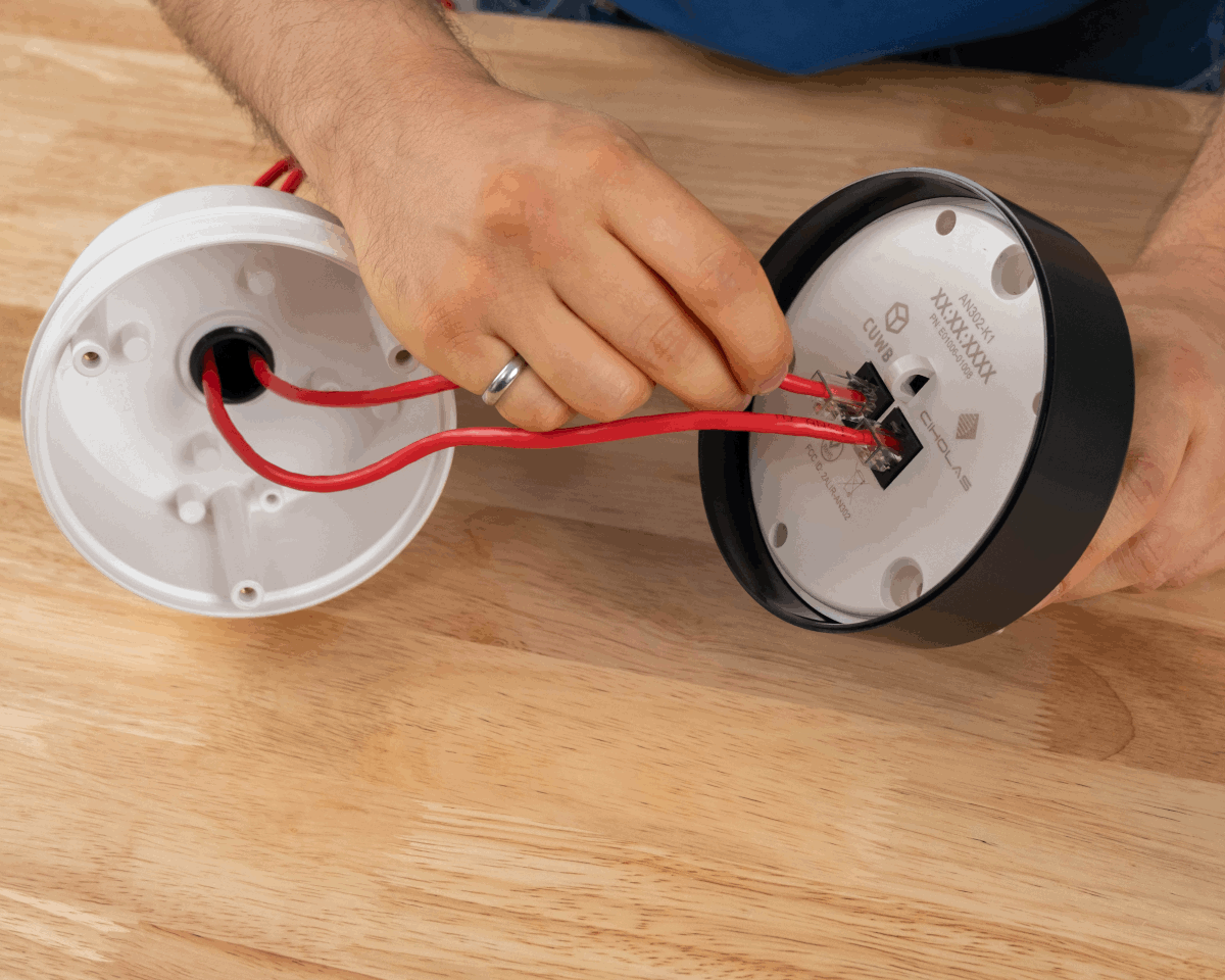
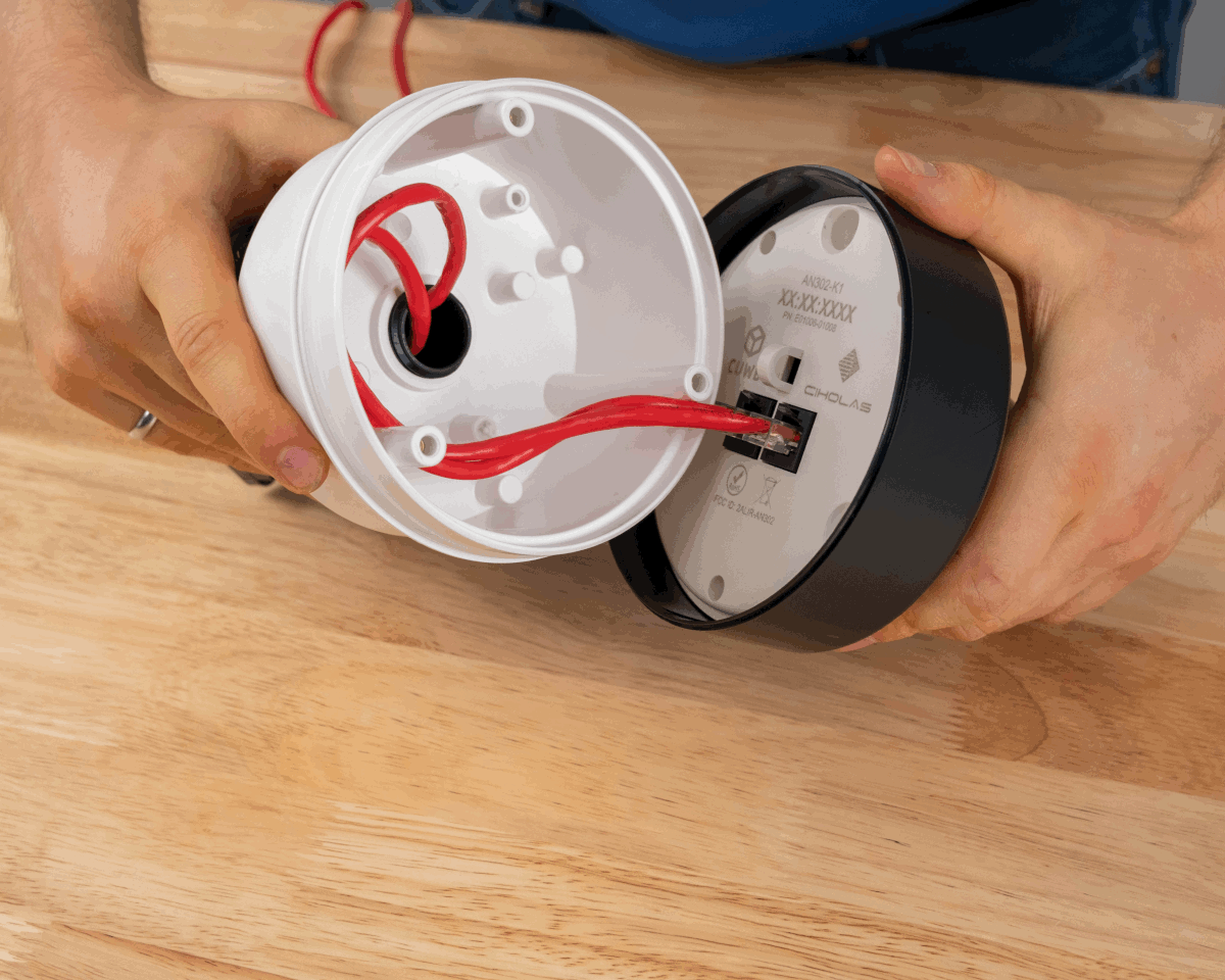
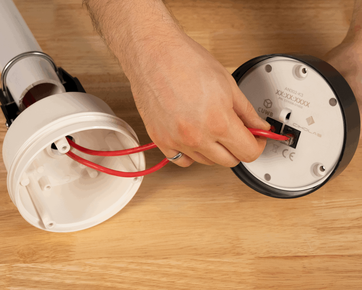
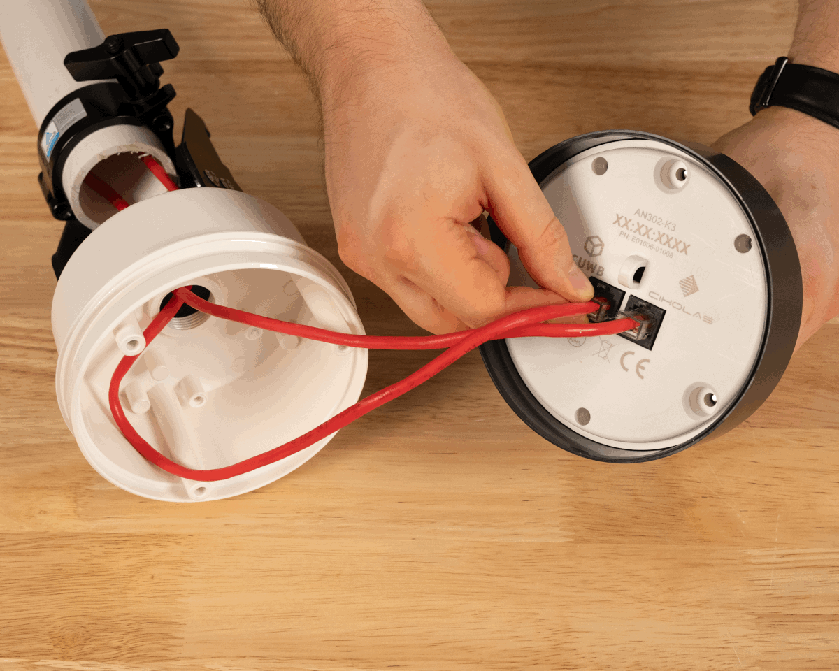
Plug the Ethernet cables into the back of the AN302 and gently insert the service loop into the mounting box.
Step 13 View of service loop -
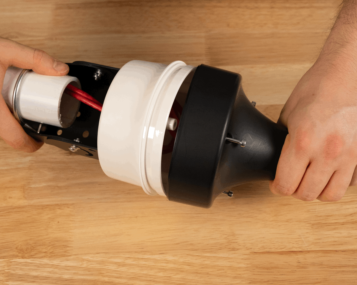
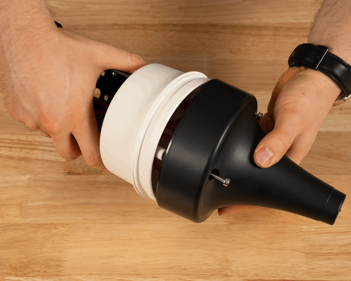
Align the AN302 backplate with the threaded bosses in the AH302. Twist to adjust as needed; press AN302 and AH302 together.
-
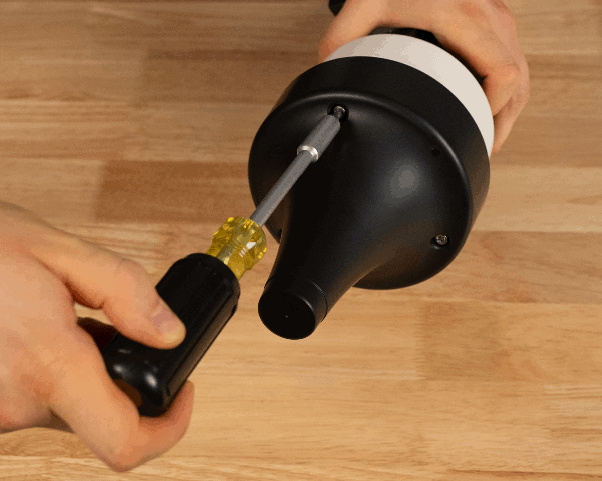
Attach AN302 to AH302 using the captive screws. Use a T20 drive set to 0.68 N-m (6 in-lb) of torque.
Step 14 Step 15
Finished View:
Unistrut Mounting
These instructions are written for use with the AH301. The AH302 may be used in its place. The instructions apply to both vertically and horizontally orientated Unistrut.
This mounting style requires additional hardware that is not provided by Ciholas.
-
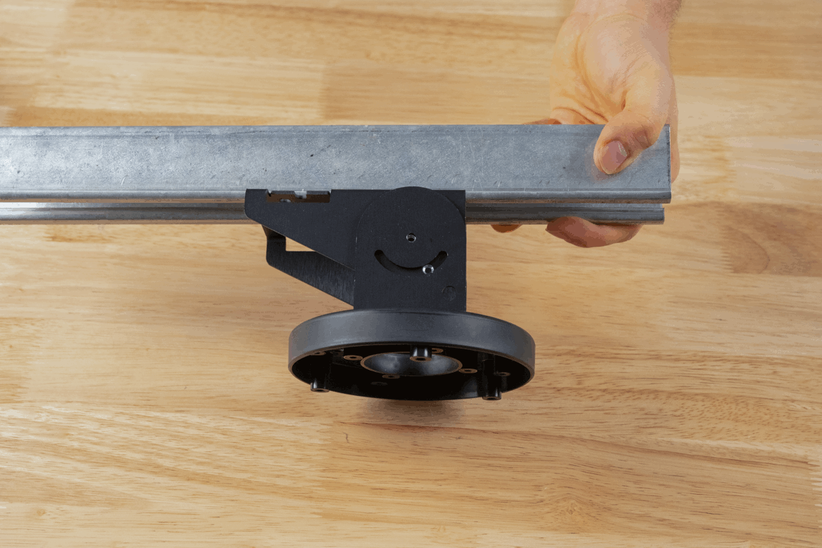
Align Part B of AB301 with the hole pattern labeled “F” on AH301.
-
Using the #8 1/2-inch self-tapping screws, attach AB301 Part B to AH302. Use four screws in total; one spare is provided by Ciholas.
Step 1 Step 2 -
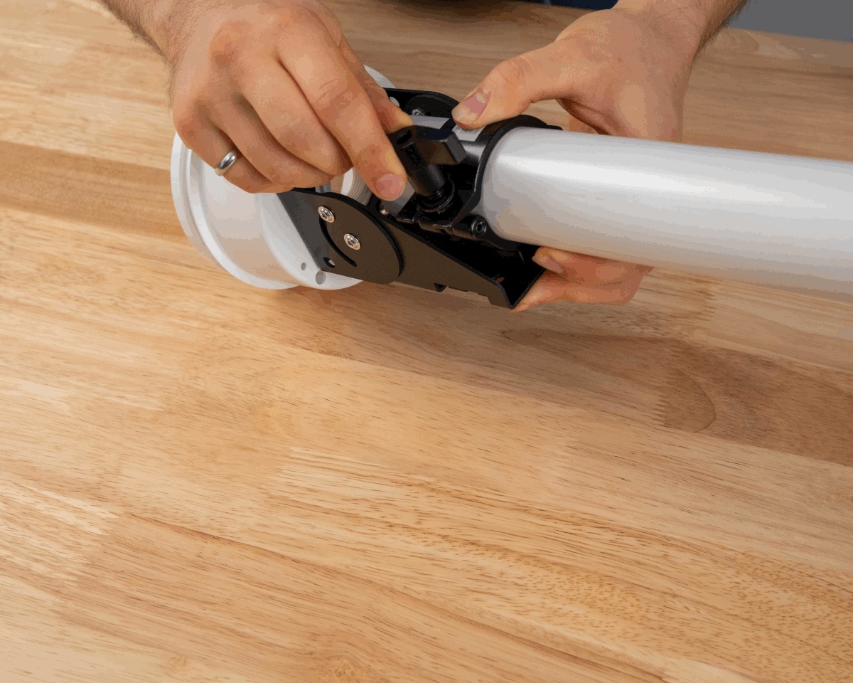
Insert channel nuts into the Unistrut channel and position appropriately.
-
Align Part A of AB301 with the Unistrut channel nuts and pass screws through the AB301 component into the channel nuts. Tighten the screws to fix the bracket component into place.


Step 3 Step 4 -
Align the assembly holes in Part B of AB301 with the threaded inserts in Part A.
-
Using the M4 8mm flanged-head screws, attach AB301 Part A to AB301 Part B. One spare screw is provided by Ciholas.
Step 5 Step 6 -
Pass Ethernet cable(s) through the back of the AH301. Provide enough cable length for a service loop to allow the AN302 to be removed and disconnected.
-
Plug the Ethernet cable(s) into the AN302 connectors.
Step 7 Step 8 -
Align the AN302 backplate with the threaded bosses in AH301. Twist to adjust as needed; press AN302 and AH301 together.
-
Attach AN302 to AH301 using the captive screws. Use a T20 drive set to 0.68 N-m (6 in-lb) of torque.
Step 9 Step 10
Finished View:

Accessories
The following accessories can be purchased from Ciholas for the Articulating Bracket.
AB302 Pipe Clamp
Contents
- (1) 51mm ID M5 U-Bolt
- (1) Sheet metal bracket
- (2) M5 Washers
- (2) M5 Nylon Insert Lock Nuts
Mechanical
 |
 |
|---|---|
| AB302 with AH301 Plate | AB302 with AH302 Box |
Assembly
 |
 |
|---|---|
| Exterior of AB301 | Interior of AB301 |
Mounting Instructions
These instructions are written for use with the AH302. The AH301 may be used in its place. AB301 is assumed to already be attached to AH302.
-
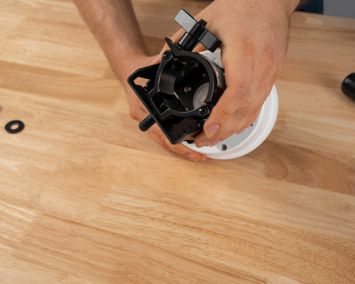
Verify that the bracket and U-bolt fit around the pipe.
-
Align bracket on interior of AB301 assembly.
Step 1 Step 2 -
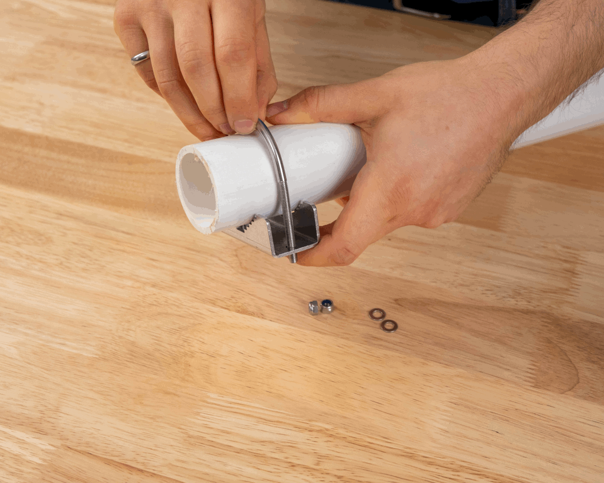
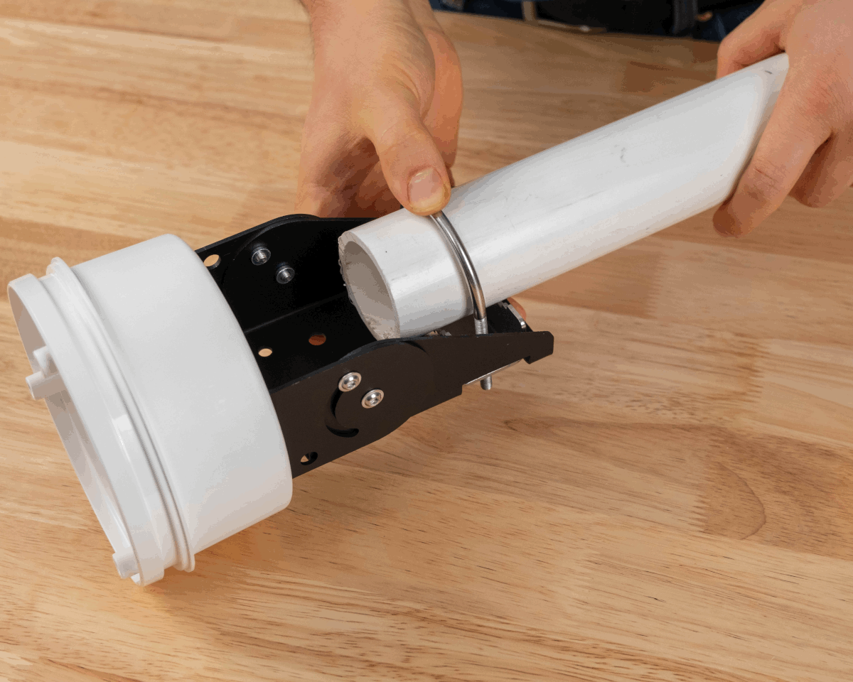
Place pipe into bracket and slip U-bolt through bracket and AB301 assembly.
-
On backside of assembly, place washers then the lock nuts on U-bolt threads. Tighten the lock nuts.
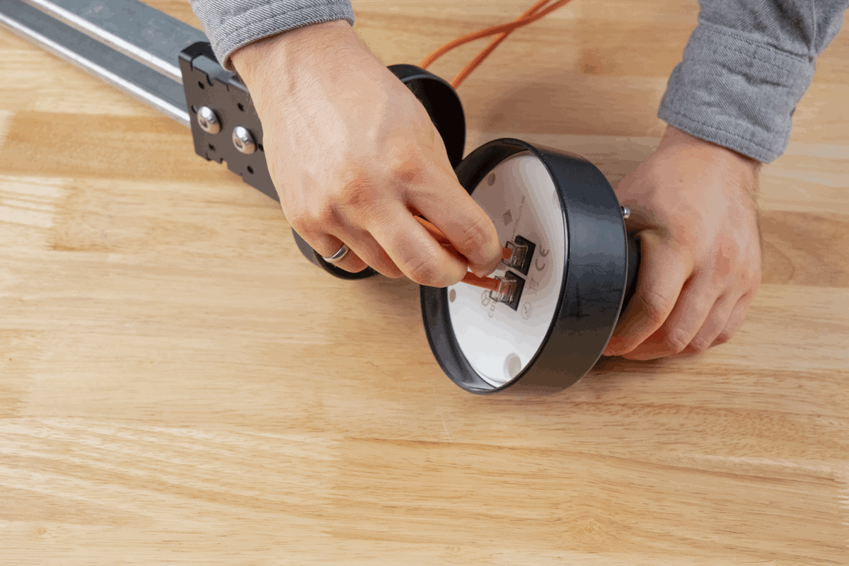
Step 3 Step 4 - Pass Ethernet cable(s) through the back of the AB301 assembly. Provide enough cable length for a service loop to allow the AN302 to be removed and disconnected.
-
Plug the Ethernet cable(s) into the AN302 connectors.
Step 5 Step 6 -
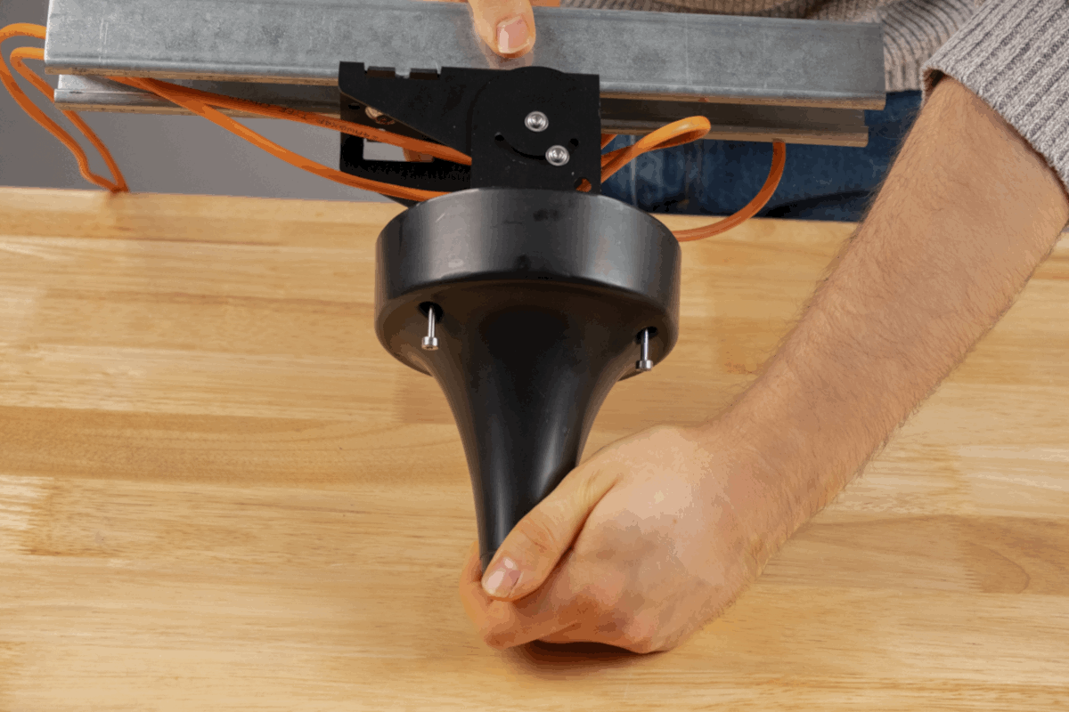
Align the AN302 backplate with the threaded bosses in AH302. Twist to adjust as needed; press AN302 and AH302 together.
-
Install AN302 to AH302 using the captive screws. Use a T20 drive set to 0.68 N-m (6 in-lb) of torque.
Step 7 Step 8
Finished Views:

AB303 Truss Clamp
Contents
- (1) Truss Clamp
- (1) M10 30mm Long Hex Head Bolt
- (1) M10 Flat Washer
- (1) M10 Split Ring Washer
- (1) M10 Nut
- (1) M10 Wing Nut
- (1) M8 Washer
- (1) M8 Wing Nut
Assembly
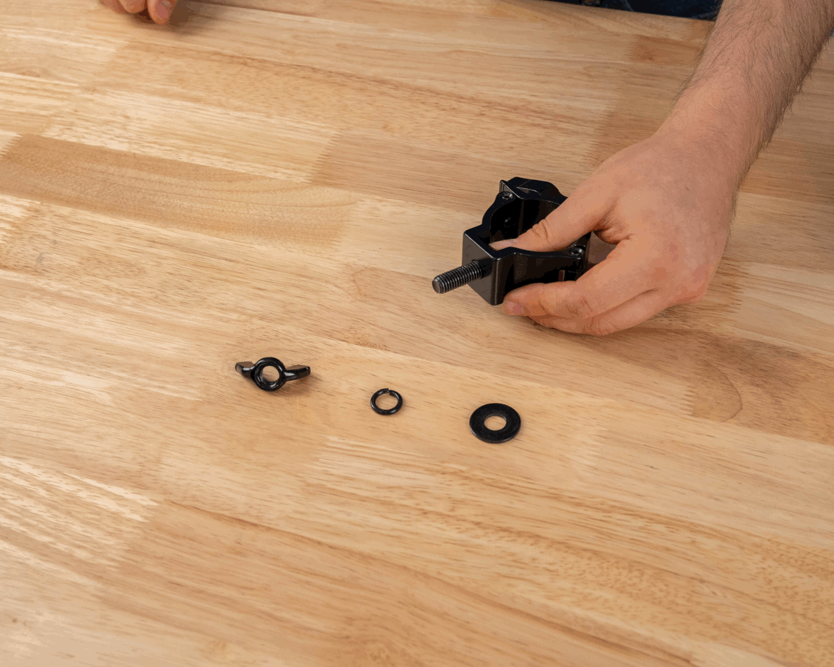
Mounting Instructions
-
Remove Wing Nut, washer and split ring washer from the clamp base post.
-
Thread clamp base post through AB301 assembly.
Step 1 Step 2 -
Replace flat washer, split ring washer and nut onto the clamp base post. Tighten nut securely.
Step 3a Step 3b -
Loosen clamp wing nut and open clamp.
-
Insert pipe into clamp. Close clamp and tighten clamp wing nut securely.
Step 4 Step 5 -
Pass Ethernet cable(s) through the back of the AB301 assembly. Provide enough cable length for a service loop to allow the AN302 to be removed and disconnected.
-
Plug the Ethernet cable(s) into the AN302 connectors.
Step 6 Step 7 -
Align the AN302 backplate with the threaded bosses in AH302. Twist to adjust as needed; press AN302 and AH302 together.
-
Attach AN302 to AH302 using the captive screws. Use a T20 drive set to 0.68 N-m (6 in-lb) of torque.
Step 8 Step 9
Finished View:
Revision
| Version | Date | Change Description |
|---|---|---|
| v5.0.1 | 2025-10-31 | Updating instruction images; Revising instructions |
| **v5.0.0 | 2025-09-15 | Initial Preliminary Release |
APPENDIX A : License Terms and Conditions
General Terms and Conditions of Purchase/Service
These General Terms of Purchase/Service are a legal Agreement between you and Ciholas, Inc. (“Ciholas”), and govern your use of all Ciholas services and products, which include, but are not limited to, CUWB.io, Ciholas.com, and all Ciholas Products, Software, and Hardware. If you are accessing and/or using any of the Ciholas services and products on behalf of your employer or as an agent of a third party, your employer or third party is bound to these terms.
Please read these General Terms carefully. Your use of these services and products indicates that you have read, understand, and agree to be bound by the terms herein. Any attempt to set up, use, or install these products constitutes your assent to all the terms of this Agreement. If you disagree with this or any of our other policies, please do not install or use our services and products, and see our return policies for instructions regarding our 60-day Money-Back Guarantee. Written approval is not a prerequisite to the validity and enforceability of this Agreement. Ciholas reserves the right to amend and/or update these terms from time to time. Such modifications to this Agreement will be posted to the website and bundled with software revisions.
This Agreement constitutes the entire and exclusive Agreement between Licensor and Licensee regarding Ciholas services and products, unless modified and agreed to in writing by both parties. We may terminate or suspend access to our services and products at any time, without prior notice or liability, for any reason whatsoever, and without limitation if you breach the General Terms. All provisions of the General Terms shall survive termination, including, without limitation, ownership provisions, warranty disclaimers, indemnity, and limitations of liability. If any provision of this Agreement is deemed invalid or unenforceable, the remaining provisions shall remain in full force and effect.
Any customized services and products will be governed under a separate Customization Agreement.
Definitions
For purposes of this Agreement, the following terms shall have the following meanings, unless the context clearly requires otherwise:
“Agreement” means this General Terms of Purchase/Service Agreement and Technology License, any exhibits or appendices attached hereto, and any documents incorporated by reference.
“Buyer” means a person or entity that purchases or contracts to purchase products, services, or property from Ciholas.
“Ciholas” means Ciholas, Inc. including any entity controlled by Ciholas, Inc.
“End-User” means the person or entity that receives and uses Ciholas services and/or products.
“Firmware” means a code segment compiled into binary machine code that is embedded inside a device.
“Hardware” means the physical components of the Ciholas UWB Systems, such as anchors, tags, and supporting equipment.
“Indemnitee” includes, but is not limited to, all End-Users, Buyers, and/or Licensees.
“License Configuration” means a particular configuration or setting provided with Ciholas services and/or products for the purposes of meeting regulatory requirements, or ensuring performance to specification.
“Licensee” means any individual or entity who purchases or uses Ciholas services and/or products covered by this Agreement.
“Licensor” means Ciholas, Inc. including any entity controlled by Ciholas, Inc.
“Our” means Ciholas, Inc. including any entity controlled by Ciholas, Inc.
“Personal Identifiable Information (PII)” means any identifying information unique to you that is made available to Ciholas when you browse our sites, create accounts on our sites, purchase and use our services and products, and/or contact us through our support phone number /email.
“Products” means any goods and/or services provided by Ciholas that are covered under this Agreement.
“Services” means services ancillary to the support and operation of Ciholas Products, Software, Firmware, or Hardware.
“Software” means programs or sets of instructions, including associated source code, object code, documentation, and data, which enable End-Users to perform specific operations or series of operations.
“Technology License” means the License granted to the Licensee for the use of Ciholas services and products through this Agreement.
“We” means Ciholas, Inc. including any entity controlled by Ciholas, Inc.
“You” means the person or entity entering into this Agreement with Ciholas.
Technology License
Subject to the terms and conditions of this Agreement, Ciholas grants to you, the Licensee, a limited, non-exclusive, license to use CUWB Software and CUWB Hardware containing Ciholas’ Intellectual Property and patent-protected technologies. Ciholas remains the owner of all titles, rights, and interests in the CUWB Software, CUWB Hardware, and other Ciholas products.
Unless expressly stated otherwise, all Software constitutes original code and is subject to the License. Any use of the Software must be in compliance with the License. You acknowledge that the Software and the underlying ideas or concepts of the services and/or products are valuable intellectual property, and you agree not to, except as expressly authorized and only to the extent applicable by statutory law, attempt (or permit others to attempt) to decipher, decompile, disassemble, modify, or otherwise reverse engineer, or attempt to reconstruct or discover any original code, underlying ideas, algorithms, interoperability of the services, products, and Software by any means. Ciholas services, products, and Software are meant to be used in conjunction with one another and any attempt to circumvent this is a violation of this License.
It is a violation of this Agreement to alter any of the Ciholas products to change their designated capability with the intent, or resulting effect, of circumventing the license configuration. Any unauthorized modification violates the terms of service and may make the products illegal in certain jurisdictions (see Government, Regulation, Jurisdiction, and Export Control below).
You must never use Ciholas services and products in any way where the failure of said services and products could cause possible harm, injury, or death to you or others.
The Licensor may amend the License at any time and will post such modifications on our website. Changes are effective upon posting. The Licensee’s continued use of the Software after such posting constitutes acceptance.
Support
Under this Agreement, Ciholas is under no obligation to provide support for any product or service (such as, but not limited to, technical support, maintenance, upgrades, modifications, or new releases) unless otherwise specified by an additional Agreement.
Indemnification
Notwithstanding any other Agreements with Ciholas, the user shall indemnify, defend, and hold harmless the Licensor, its employees, successors, and heirs against any claim, liability, cost, damage, deficiency, loss, expense, or obligation of any kind or nature (including, without limitation, reasonable attorney’s fees and other costs and expenses of litigation) incurred by or imposed upon the indemnitees, or any one of them, in connection with any claims, suits, actions, demands, or judgments (including, but not limited to, actions in the form of tort, warranty, or strict liability) arising from the use of Ciholas software and products.
Force Majeure
Ciholas shall not be liable or responsible to you for any failure or delay in fulfilling or performing any term of this Agreement, when and to the extent that, such failure or delay is caused by or results from acts beyond Ciholas’ reasonable control, including, but not limited to, acts of nature, natural disasters, war, terrorism, labor disputes, supply chain disruptions, power outages, or governmental restrictions.
Government Regulation, Jurisdiction, and Export Control
Ciholas products are subject to governmental regulations and laws that may vary by state and country. By purchasing Ciholas products, you agree you will not ship, transfer, or export said products in any manner prohibited by law. You also warrant and agree that you are not located in, under the control of, or a national or resident of any of the countries defined by the Office of Foreign Assets Control, which include, but may not be limited to, Cuba, Iran, North Korea, and Syria. In addition to embargoes, other countries and/or regions may face restrictions under various U.S. export control regulations or be the target of sanctions governed by the Export Administration Act of 1979 (EAA), as amended, any successor legislation, the Export Administration Regulations (EAR), and the International Traffic in Arms Regulations (ITAR). You will comply in all respects with the export and reexport restrictions applicable to Ciholas products and will otherwise comply with the EAA, EAR, ITAR, and other United States laws and regulations in effect from time to time.
In addition to export regulations, the United States and other countries have laws and regulations governing the use of radio frequency (RF) devices. In the United States, such regulation is under Title III of the Communications Act of 1934, as amended, and regulated by the Federal Communications Commission (FCC). The FCC oversees all non-Federal uses of the radio frequency spectrum, while other regulatory bodies oversee RF devices in other countries’ jurisdictions. You agree that you will only use Ciholas products in the jurisdiction for which they were certified and will not exceed the products’ operational and use limitations as stated in the product manual. All Ciholas products are labeled as to their specific jurisdictional certification in accordance with the laws of that jurisdiction.
Governing Law
This Agreement will be governed by the laws of the State of Indiana, USA. Parties agree to attempt, in good faith, to resolve and settle any dispute arising out of this Agreement through negotiation between officially authorized representatives of each party. If the dispute is not resolved through negotiation, any litigation arising from the use of Ciholas services and/or products must be brought and resolved in the State of Indiana, USA.
60-Day Money-Back Guarantee
All standard Ciholas products not covered by another agreement have a 60-day Money-Back Guarantee. If for any reason the performance of any product is not acceptable, the product may be returned to Ciholas for a refund. Please note: bulk orders are not eligible for the money-back guarantee and cannot be canceled once the order is processed.
Shipping costs and any taxes and/or duties are not refundable and there is a 20% restocking fee for all returns under this policy. To be eligible for a refund, a customer must include an RMA# (see our return process) and dated proof of purchase with the item for return. The cost of the return shipment, including all taxes and duties, is at the buyer’s expense. Any product returned not in resalable condition will not be refunded.
Limited Warranty
Ciholas warrants that all Ciholas manufactured products, excluding software, will be free from any defect in materials or workmanship for a period of one year. Warranty begins on the date that an item is shipped from Ciholas to the buyer. The warranty is non-transferable and is extended only to the original buyers of this product when the product is used for the purpose for which it was intended. The one-year warranty covers only defects arising under normal use and does not include malfunctions or failures resulting from misuse, abuse, neglect, alteration, improper installation, acts of nature, tampering, or any repairs attempted by anyone other than Ciholas. During the one-year warranty period, the customer’s sole and exclusive remedy will be, at Ciholas’ sole discretion, the repair or replacement of the defective product, or refund of the purchase amount of the product. Ciholas reserves the right to substitute functionally equivalent new or serviceable used parts.
To be entitled to the rights provided by the one-year warranty, the customer must do the following:
- Contact Ciholas Technical Support at returns@ciholas.com or 1-844-595-TECH (8324).
- Provide in email/phone call, all model number(s), serial number(s), and proof of purchase for all items affected.
- If return/exchange is necessary, customer will be given a Returned Material Authorization (RMA) # to include with their return.
- The customer must then ship the item(s), at their expense (including all duties and taxes), to the address provided in the RMA authorization.
- Once a product arrives at Ciholas, return shipment of repaired or replaced product(s) or a refund will be sent to the customer. The method of return shipment is at Ciholas’ discretion and expense, except for applicable duties and taxes, which are the responsibility of the buyer.
Product Warranty Exclusions
Ciholas does not warrant or guarantee, and is not responsible for the following:
- Defects, failures, damages, or performance limitations caused in whole or in part by: (A) power failures and surges; fires; floods; acts of nature; excessive temperatures; corrosive environments; accidents; actions by third parties; or other events outside of Ciholas’ control; or (B) customer abuse; mishandling; misuse; negligence; improper storage, servicing, installation, or operation; or unauthorized attempts to repair or alter equipment in any way.
- Performance of the equipment when used in combination with equipment not purchased, specified, or approved by Ciholas.
- Consumable goods used with, or required by, Ciholas products.
- Alterations and/or modifications to any Ciholas equipment without Ciholas’ written authorization. Such action unconditionally VOIDS the Ciholas Agreement and Warranty.
- Installation of any software code, other than that provided and licensed by Ciholas. Any such installation onto any Ciholas product voids the one-year warranty, unless a written exemption is provided to the customer by Ciholas.
Disclaimer of Warranty
CIHOLAS SERVICES, PRODUCTS, AND ALL INFORMATION, CONTENT, MATERIALS, (INCLUDING SOFTWARE AND HARDWARE), AS WELL AS OTHER SERVICES MADE AVAILABLE THROUGH CIHOLAS, ARE PROVIDED ON AN “AS IS” AND “AS AVAILABLE” BASIS, UNLESS OTHERWISE SPECIFIED IN WRITING. CIHOLAS SERVICES INCLUDE ALL CIHOLAS OWNED AND OPERATED DOMAINS, INCLUDING, BUT NOT LIMITED TO, CIHOLAS.COM, CIHOLAS SHOP, CUWB.IO, AND ALL CIHOLAS PRODUCTS, SOFTWARE, AND HARDWARE. THE USE OF CIHOLAS SERVICES AND PRODUCTS IS AT THE USER’S SOLE RISK.
EXCEPT AS EXPRESSLY PROVIDED IN THE CIHOLAS WARRANTY POLICY STATEMENT, CIHOLAS HEREBY EXPRESSLY DISCLAIMS ALL REPRESENTATIONS, CONDITIONS, AND WARRANTIES, WHETHER EXPRESS OR IMPLIED, INCLUDING, BUT NOT LIMITED TO, IMPLIED WARRANTIES OF TITLE, MERCHANTABILITY, NON-INFRINGEMENT, AND FITNESS FOR A PARTICULAR PURPOSE. IN NO EVENT SHALL CIHOLAS BE LIABLE TO THE USER OR ANY OTHER PARTY FOR ANY DIRECT, INDIRECT, GENERAL, SPECIAL, INCIDENTAL, CONSEQUENTIAL, EXEMPLARY, OR OTHER INJURIES AND/OR DAMAGES ARISING OUT OF THE USE OR INABILITY TO USE CIHOLAS SERVICES AND PRODUCTS (INCLUDING, WITHOUT LIMITATION, DAMAGES FOR LOSS OF BUSINESS PROFITS, BUSINESS INTERRUPTION, LOSS OF INFORMATION, BREACH OR ANY OTHER PECUNIARY LOSS), OR FROM ANY BREACH OF WARRANTY. NOTWITHSTANDING ANYTHING TO THE CONTRARY CONTAINED IN THIS DISCLAIMER OF WARRANTY, IN NO CASE SHALL THE MAXIMUM AGGREGATE LIABILITY OF CIHOLAS TO THE USER EXCEED THE TOTAL AMOUNT OF THE ACTUAL FEES PAID BY THE USER TO CIHOLAS.
CIHOLAS IS NOT LIABLE FOR ANY CONDUCT OF ANY USER OF CIHOLAS SERVICES AND PRODUCTS, NOR FOR ANY APPLICATION OR USE OF CIHOLAS SERVICES AND PRODUCTS IN AN ILLEGAL MANNER, TO COMMIT AN ILLEGAL ACT, OR IN A JURISDICTION IN WHICH IT IS ILLEGAL OR UNAUTHORIZED TO USE THESE SERVICES AND PRODUCTS. IT IS THE RESPONSIBILITY OF THE USER OF CIHOLAS SERVICES AND PRODUCTS TO ESTABLISH THE LEGALITY OF ITS USE IN THE USER’S JURISDICTION.
Ciholas Standard Privacy Policy
Ciholas is committed to protecting your personal information and your right to privacy. If you have any questions or concerns about our policy or our practices with regards to your personal information, please notify Ciholas at info@ciholas.com.
The following is to inform you of our policies for collecting, using, and disclosing your Personal Identifiable Information (PII) made available to Ciholas when you browse our sites, create accounts on our sites, purchase and use our services and products, and/or contact us through our support email. By using any of our services and products, you agree to the collection and use of your PII in accordance with this and other policies contained in this Agreement.
Personal Identifiable Information Collected
In the CUWB.IO Shop, we collect personal information that you voluntarily provide to Ciholas when creating an account, posting messages, or otherwise contacting us. The PII that we collect depends on the context of your interactions with Ciholas and the choices you make regarding the information you provide. The PII you share is up to you and is not required for browsing any of our sites. However, if you want to create an account, purchase an item in our shop, and/or call/email our support staff, you may be asked for PII. The PII collected is encrypted using secure socket layer technology (SSL).
The PII we collect could include the following:
Name and Contact Data – First and last name, email address, postal address, phone number, and other similar contact data.
Credentials – Passwords and similar security information used for authentication and account access.
Payment Data – All payment data collected through the website is by a third-party payment processor (TPPP). Ciholas DOES NOT have access to any of the payment information that you provide to the TPPP. None of the TPPPs use any of your data for anything other than processing your payment and have their own privacy policies, which are as strict as or stricter than, those contained in this privacy policy. Ciholas and all Ciholas TPPPs use SSL/TLS encryption for securing data. All Ciholas TPPPs are PCI DSS compliant for payment processing standards.
Information Usage
We use your PII for the purposes listed above and to keep our site safe and secure (for example fraud monitoring and prevention) and to enforce our terms, conditions, and policies for our legitimate business purposes.
We may disclose your information where we are legally required to do so to comply with applicable law, judicial proceedings, court order, or legal process, such as in response to a court order or a subpoena.
We will not share, sell, rent, or trade any of your PII with any third parties.
Duration of PII Storage
We keep your information for only as long as necessary to fulfill the purposes outlined in this privacy policy unless otherwise required by law.
Keeping PII Safe
We have implemented appropriate technical and organizational security measures designed to protect the security of any personal information we process. However, given that the internet is not 100% secure, transmission of personal information to and from our sites is at your own risk. Only access our services, products, and sites within a secure environment.
Unique Privacy Rights
Based on the laws of some countries and states, you may have the right to request access to the PII we collect from you, change that information, or delete it in some circumstances. For more information on how to do that, please contact Ciholas at info@ciholas.com.
If you are visiting our sites from outside of the United States, please be aware that you are sending information (including PII) to the United States where our servers are located. That information may then be transferred within the United States or back out of the United States to other countries outside of your country of residence, depending on the type of information and how it is stored by us. These countries, including the United States, may not have data protection law as comprehensive or protective as those in your country of residence; however, our collection, storage, and use of your PII will at all times continue to be governed by this Privacy Policy.
Non-PII Information Automatically Collected
We automatically collect certain information through web analytics when you visit, use, or navigate any of our sites. This information does not reveal your specific identity, but may include device and usage information, such as your computer’s Internet Protocol (IP) address, browser type, browser version, operating system, referring URLs, country, location, the pages of our sites that you visit, the time and date of your visit, the time spent on those pages, and other similar statistics. This information is primarily needed to maintain the security and operation of our sites and for our internal analytics and reporting purposes.
We collect this information using cookies. Cookies are small pieces of text stored on a user’s computer. They can be accessed by the web server or the client computer, allowing the server to deliver information tailored to the user. Most web browsers are set to accept cookies by default. We use cookies to keep track of items stored in your shopping basket, to conduct research and diagnostics to improve our content, services, and products, to prevent fraudulent activity, and to improve security.
If you prefer, you may choose to set your browser to remove and reject cookies. This could affect the availability of certain features, services, or products on our sites. Most browsers allow you to turn off cookie collection in their Tools/Settings button under a Privacy tab.
These Terms of Service were last modified on 2025-11-11.
[End of Agreement]